Service work
490E75=0_C
98 | Ottobock
4.14.11 Removing/installing the manual back angle adjustment (VAS seat)
INFORMATION
The manual back angle adjustment (VAS seat) is replaced together with the upper connecting tube. The release
strap with locking bolts can be replaced separately.
When changing the back angle adjustment type (mechanical or power back angle adjustment), additional adjust-
ments such as additional control modules, new cabling or reprogramming the control unit may be required. Con-
tact your national Ottobock team before changing the back angle adjustment type.
f
Prerequisites:
Switch off the control unit and deactivate the main fuse (see Page 15).
Remove the seat cushion and back padding.
f
Tools: Allen wrench size 6; open-ended or ring wrench size 13; torque wrench with Allen insert size 6
Removing the manual back angle adjustment (VAS seat)
1) Remove the cover from both bearing plates (see Page 91).
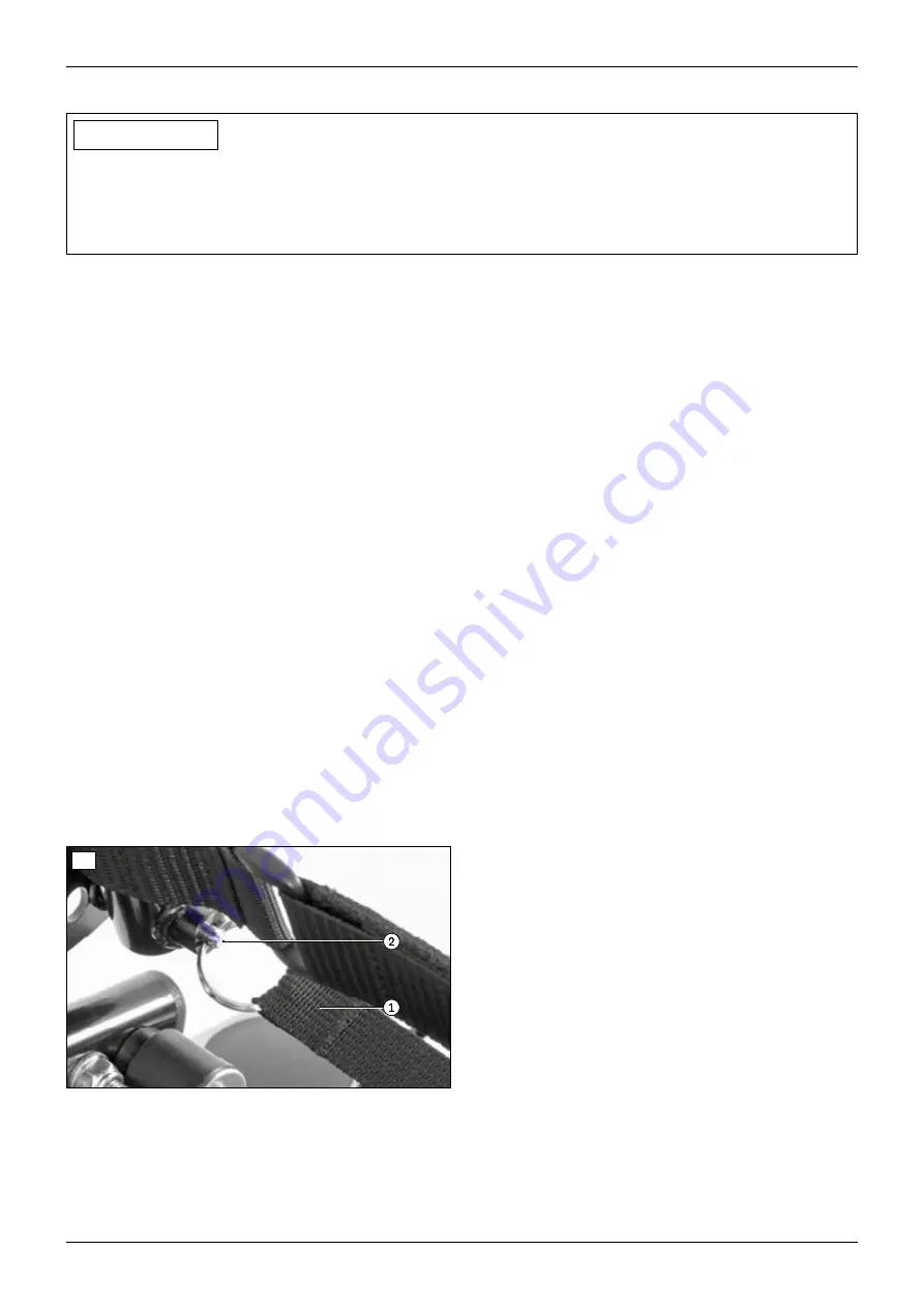
2) Pull the release strap (see Fig. 206, item 1) and fold the back forwards onto the seat.
3) Loosen and remove the 4 screws and nuts on the upper connecting tube (see Fig. 201, item 1). Remove the seat
module (optional) as you do so (see Fig. 201, item 2; see Page 25).
4) Loosen the 2 clamping screws on the upper connecting tube on both sides (see Fig. 202, item 1).
5) Pull the inner tubes out of the upper connecting tube on both sides (see Fig. 202, item 2).
6) Remove the upper connecting tube. Remove the cable attachments if necessary (see Fig. 202, item 3).
7) Rotate the key ring on the release strap out of the eyelet of the locking bolt on both sides (see Fig. 206, item 2).
8) Remove the locking bolt with compression spring from the back tube on both sides.
9) Optional: Install the power back angle adjustment (see Page 96).
Installing the manual back angle adjustment (VAS seat)
1) Optional: Remove the power back angle adjustment (see Page 96).
2) Insert the locking bolt with compression spring into the back tube on both sides.
3) Turn the key ring on the release strap into the eyelet of the locking bolt on both sides (see Fig. 206, item 2).
4) Insert the upper connecting tube and slide the inner tubes (see Fig. 202, item 2) into the upper connecting tube
on both sides.
5) IN@MOOC@ÁN>M@RN<I?IPONDIOJOC@<KKMJKMD<O@NGJONDIOC@PKK@M>JII@>ODIBOP=@<I?uMHGTODBCO@IOC@HN@@
Fig. 201, item 1). Attach the seat module (optional) as you do so (see Fig. 201, item 2; see Page 25).
6) Firmly tighten the 2 clamping screws on the upper connecting tube on both sides (see Fig. 202, item 1).
7) Reattach the loosened cable attachments (see Fig. 202/203, item 3).
8) Pull the release strap (see Fig. 206, item 1) and fold the back to the rear and engage it.
9) Attach the cover for both bearing plates (see Page 91).
206
Summary of Contents for 490E75 Series
Page 1: ...490E75 0_C Service manual...
Page 38: ...Service work 490E75 0_C 38 Ottobock 57 58 59 60 61 62 63...
Page 41: ...Service work 490E75 0_C Ottobock 41 70 71 72 73 74 tt 75 76...
Page 55: ...Service work 490E75 0_C Ottobock 55 103 104 105 106 107 108 109 110...
Page 108: ...Service work 490E75 0_C 108 Ottobock 227 228 229 t 230 231 232...
Page 112: ...Service work 490E75 0_C 112 Ottobock 237 238 239 240 241...
Page 143: ...R Net wheelchair control 490E75 0_C Ottobock 143 Seat module pin assignment 287...
Page 161: ...490E75 0_C Ottobock 161...
Page 162: ...490E75 0_C 162 Ottobock...


