background image

Use

Invader Pointer

Ottobock  |  11 

CAUTION


Improper use of self-locking nuts

Tipping, falling over of the user due to screw connections coming loose


f

Always replace self-locking nuts with new self-locking nuts after disassembly�

Adjustments to match the concrete physical and mental condition of the user should always be made in the user's 

presence�

All parts of the product should be cleaned thoroughly before adjustments are made�

Please note the following instructions when carrying out any adjustment:

•  Adjust the wheelchair such that the seat bottom is horizontal or tilted to the rear�

•  Adjust the centre of gravity such that the user can push the rear wheels as effectively as possible�

•  Adjust the height of the side panels such that their upper edge is as parallel to the rear wheels as possible�

•  Adjust the wheelchair such that the front frame tubes do not protrude beyond the bumper�

Concrete settings (e�g� seat and back upholstery etc�) are described in the following sections with the respective 

components�

The tools required for adjustments and maintenance tasks as well as the torque values for screw connections are 

listed in the section "Technical data" (see Seite 29 ff�)�

7.3    Seat

WARNING


Seat cushion and back pad may ignite

Burns due to user error


f

The seat and backrest upholstery as well as padding fulfil the requirements for flame resistance according to 

ISO 8191-2 and DIN EN 1021-2� However, they may still ignite if fire is handled improperly or negligently�


f

Keep away from all ignition sources, especially lit cigarettes�

NOTICE

Wear of the seat and back upholstery

Loss of functionality due to unallowable continued use


f

Replace the seat and back upholstery promptly in case of damage�

The seat cushion and the seat upholstery ensure pressure relief during use of the wheelchair� They can be adjusted 

according to the needs of the user�

7.3.1    Optional: removing and fastening the seat cushion

The seat cushion can be removed for cleaning�

1)  Remove the seat cushion from the seat pad�

2)  After  cleaning  (see  Seite  23):  Fit  the  seat  cushion  on  the  seat  pad�  The  seat  cushion  is  secured  against 

sliding by being pressed on to the hook-and-loop fastener�

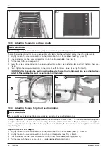
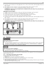
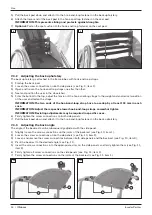
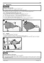
7.3.2    Adjusting the seat upholstery

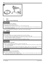
The seat upholstery is attached to the frame tubes by 2 upholstery bars and is tensioned on one side with a hook-

and-loop closure on the underside�

1)  Optional: Remove the seat cushion from the seat pad�

2)  Loosen the screw connections on the upholstery bars (see Fig� 3, item 1)�

INFORMATION: Loosen the screw connections only until the seat upholstery underneath can be moved.

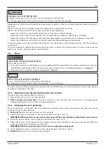
3)  Open the hook-and-loop closure along the upholstery bar (see Fig� 4)

4)  Adjust the tension of the seat pad to the weight and anatomical condition of the user and securely fasten the 

hook-and-loop closure along the upholstery bar�

INFORMATION: The hook-and-loop closure must completely overlap itself.

5)  Firmly tighten the screw connections on the upholstery bars (see Fig� 3, item 1)�

6)  Optional: Attach the seat cushion to the seat pad�

Summary of Contents for Invader Pointer

Page 1: ...Invader Pointer Instructions for use 3...

Page 2: ...Invader Pointer 2 Ottobock...

Page 3: ...2 7 4 Backrest 13 7 4 1 Fastening and removing the back pad 13 7 4 2 Adjusting the back upholstery 14 7 4 3 Adjusting the back angle 14 7 5 Side panels 15 7 5 1 Adjusting the height of the side panels...

Page 4: ...n maintenance 24 8 2 Inspection 24 8 3 Repair 25 8 3 1 Inner tube rim tape and tyre replacement 25 8 3 2 Replacing the side panels 26 8 3 3 Replacing the seat upholstery 27 8 3 4 Replacing the back up...

Page 5: ...or back page for addresses Service and repairs to the product may only be carried out by qualified personnel If you have any problems please contact your dealer This ensures that any necessary repair...

Page 6: ...eelchair features can be adjusted Seat height Seat inclination Centre of gravity Back angle Legrest The frame material and its processing ensure great stability and durability The rear wheels are atta...

Page 7: ...ach of children Risk of hand injuries CAUTION Pinching on components Pinching crushing due to lack of caution in danger areas f f Do not reach between the rear wheel and side panel when driving your w...

Page 8: ...se the product to any extreme temperatures e g direct sunlight extreme cold Hazards due to improper use of the product WARNING Overloading Severe injuries if the wheelchair tips over due to overloadin...

Page 9: ...ambient temperature between 10 C and 40 C must be maintained Tyres contain chemical substances that can react with other chemical substances such as cleaning agents acids etc 6 Preparation for use 6 1...

Page 10: ...h the user seated all hook and loop connections must be firmly fastened and all screw connections must be firmly tightened f f Check the product for safety and functionality after changing the setting...

Page 11: ...However they may still ignite if fire is handled improperly or negligently f f Keep away from all ignition sources especially lit cigarettes NOTICE Wear of the seat and back upholstery Loss of functi...

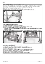
Page 12: ...tion must also be readjusted see Seite 12 The seat bottom must be horizontal or tilted back 5 6 7 3 4 Adjusting the seat height and seat inclination INFORMATION The assembly tasks described below may...

Page 13: ...nection on both perforated plates see Fig 6 item 1 CAUTION The front and rear seat height must be coordinated with one another The seat bottom must be horizontal or tilted back 7 7 4 Backrest WARNING...

Page 14: ...loop strap have to overlap by at least 100 mm in each case INFORMATION Adjust the respective lower hook and loop straps somewhat tighter INFORMATION Deviating adjustments may be required in specific c...

Page 15: ...panel and backrest 3 Pivot the side panel to the desired height see Fig 13 4 Insert the screw connection into the appropriate slot on the backrest and firmly tighten it 5 Firmly tighten all screw conn...

Page 16: ...ctions on the footplate see Fig 16 item 1 2 Move the footplate to the desired position on one of the 3 levels INFORMATION If the legrest is equipped with lateral heel blocks the adjustment range of th...

Page 17: ...el CAUTION Defective tyres Accidents falling due to poor traction reduced braking force or lack of manoeuvrability f f Maintain sufficient tyre pressure The correct tyre pressure is printed on the tyr...

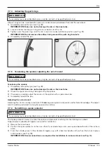
Page 18: ...track width INFORMATION The assembly tasks described below may only be carried out by qualified personnel The track width of the rear wheels can be subsequently adjusted within a narrow range This mak...

Page 19: ...o damage the rim or the inner tube 2 Check the spoke tension by shaking moving the spokes 3 If necessary carefully adjust the tension of the spokes with a spoke tensioner 4 Completely reinstall the ty...

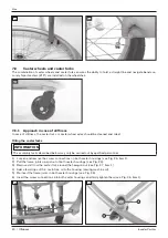
Page 20: ...caster forks INFORMATION The assembly tasks described below may only be carried out by qualified personnel 1 Loosen and remove the screw connections on both caster housings see Fig 26 item 1 2 Pull t...

Page 21: ...tion see Fig 28 item 1 2 Remove the caster wheel axle spacers see Fig 28 item 2 3 Remove and replace the caster wheels 4 Install the caster wheels together with the spacers Tighten the caster wheel ax...

Page 22: ...tach the protective pad and fasten the hook and loop closure see Fig 32 7 9 2 Approach in case of stiffness In case of stiffness the anti tipper wheel axle should be cleaned and oiled 1 Remove dirt fr...

Page 23: ...duct is used by more than one person using a conventional disinfectant is required Only use colourless water based disinfectants Observe the instructions for use provided by the manufacturer 8 Mainten...

Page 24: ...e wheelchair If a screw connection loosens repeatedly contact the dealer who issued the product to you or the manufacturer s service promptly Hair and dirt particles generally accumulate between the c...

Page 25: ...s Driving test 8 3 Repair 8 3 1 Inner tube rim tape and tyre replacement CAUTION Improper tyre replacement Injuries to the user due to incorrect installation product damage f f No person is permitted...

Page 26: ...d rim during this process 36 37 Inflating the tube 1 Ensure that the valve is positioned perpendicularly for proper positioning of the tube and tyre in the region of the valve 2 Firmly screw on the va...

Page 27: ...upholstery with the upholstery bars on the frame tubes INFORMATION Align the seat pad with the centre hook and loop strip towards the backrest see Fig 40 6 Adjust the seat upholstery and firmly tight...

Page 28: ...fe 4 years The design manufacturing and requirements for the intended use of the product are based on the expected service life These also include the requirements for maintenance ensuring effectivene...

Page 29: ...res Tubeless indoor sport tyres 8 11 16 Temperatures Ambient temperature C 20 to 40 Storage temperature C 10 to 40 Weights Maximum load capacity maximum user weight kg 120 11 2 Required tools The foll...

Page 30: ...Invader Pointer 30 Ottobock...

Page 31: ...0 212 3565040 F 90 212 3566688 info ottobock com tr www ottobock com tr Africa Otto Bock Alg rie E U R L 32 rue Ahc ne Outaleb Coop rative les Mimosas Mackle Ben Aknoun Alger DZ Alg rie T 213 21 91386...

Page 32: ...Otto Bock Mobility Solutions GmbH Lindenstra e 13 07426 K nigsee Rottenbach Germany www ottobock com Ihr Fachh ndler Your specialist dealer Ottobock 647G1254 EN 02 1704...

Reviews: