481G74=SE002 Drive wheel adapter
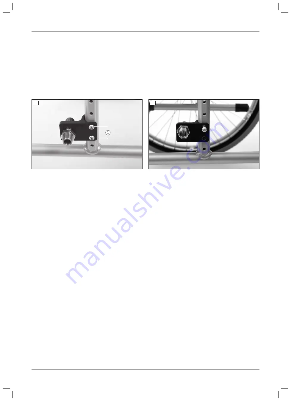
Horizontal adjustment of the drive wheels within the drive wheel adapter is not possible. However, the depth can
be adjusted by turning the drive wheel adapter.
1) Remove the wheels.
2) Remove the Allen head screws/counter nuts between the drive wheel adapter and frame tube (see fig. 4,
item 1).
3) Turn the drive wheel adapter. The flat side still has to face out (see fig. 5).
4) Install the drive wheel adapter together with the Allen head screws/counter nuts (see fig. 5, item 1).
5) If necessary, change the height of the drive wheel adapter in the slotted hole (see previous section).
6) Tighten the Allen head screws/counter nuts to
7 Nm
.
4
5
481G74=SE006 Drive wheel adapter
The horizontal position of the drive wheels is adjusted by moving the fitting in the drive wheel adapter.
1) Remove the wheels.
2) Loosen and remove the respective countered hexagon nut on the fitting (see fig. 6; wrench size 24 mm).
3) Insert the fitting in the desired slot.
4) Tighten the countered hexagon nut to
50 Nm
on each side.
→
Once changed, the left and right fittings must both have the same horizontal position.
Increasing the wheelbase by using the wheelbase extension
The wheelbase can be further increased by installing the alternative 481G74=LE009 drive wheel adapter (see
fig. 7). This makes the setting even more passive.
1) Remove the drive wheel adapter (see fig. 2).
2) Bring the alternative drive wheel adapter together with the Allen head screws/counter nuts into the desired pos
ition.
INFORMATION: If required, the height of the drive wheel can be changed slightly with this drive wheel
adapter by turning it 180°.
3) Tighten the Allen head screws/counter nuts to
7 Nm
(see fig. 7, item 1).
4) Insert the fitting into the bore for the extended wheelbase (see fig. 7, item 2).
5) Tighten the respective countered hexagon nut to
50 Nm
(see fig. 6).
→
Once changed, the left and right fittings must both have the same horizontal position.
11
Start M2S, Start M2
Settings


