6.4 Adjusting the wheel locks
WARNING
Failure to verify brake functionality
Accident, user falls due to incorrect adjustment and improperly inflated tyres
►
Check the correct spacing between the wheel lock bolt and tyre (see the following section for details).
►
Check the correct position of the wheel lock bolt relative to the tyre. During braking, the wheel lock bolt has to
cover at least half the tyre width.
►
Always carry out adjustments to the wheel lock on both sides.
►
Ensure that the user can operate the wheel lock without great effort. The force required to do so must not
exceed 60 N.
►
Check the tyre pressure of the drive wheels. Note the information in the section “Technical data” or on the tyre
sidewall.
►
Only use original drive wheels with a verified maximum radial out-of-round of
1 mm
.
This adjustment must be made after the drive wheel has been repositioned or during fine adjustment.
6.4.1 Adjusting the knee lever wheel locks
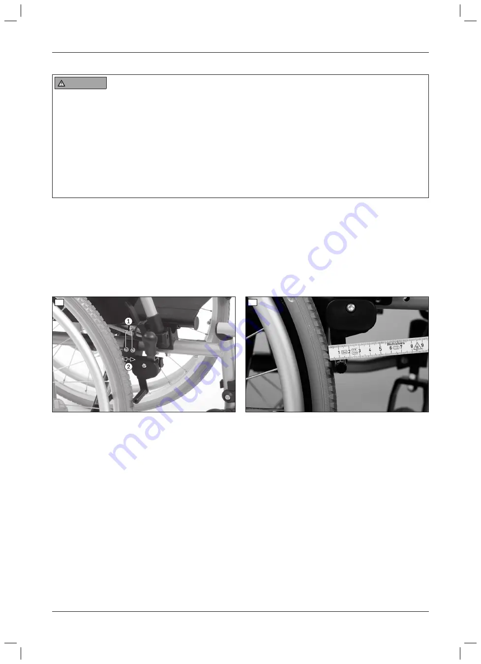
1) Loosen the Allen head screws on the clamp bracket (see fig. 17, item 1).
2) The knee lever wheel lock is continuously moveable and adjustable (see fig. 17, item 2).
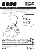
When the wheel lock is disengaged, the gap between the tyre and wheel lock bolt must not exceed
5 mm
(see
fig. 18).
Ensure that the wheel lock bolt covers at least half the tyre width during braking.
3) Tighten the Allen head screws to
16 Nm
.
→
After adjustment, the left and right knee lever wheel locks must both have the same braking force.
17
18
6.4.2 Adjusting the knee lever wheel lock for one-handed operation
Presetting (as needed)
1) Loosen the Allen head screws on the clamp bracket (see fig. 19, item 1; see fig. 20, item 1).
2) Adjust/move the wheel lock support in the clamp bracket (see fig. 19, item 2; see fig. 20, item 2).
When the wheel lock is disengaged, the gap between the tyre and wheel lock bolt must not exceed
5 mm
.
Ensure that the wheel lock bolt covers at least half the tyre width during braking.
3) Tighten the two Allen head screws to
16 Nm
.
Fine adjustment
1) Loosen the Bowden cable mounting (see fig. 20, item 3).
2) Adjust the length of the Bowden cable.
3) Clamp the Bowden cable again by tightening the mounting.
→
After adjustment, the left and right knee lever wheel locks must both have the same braking force.
4)
If necessary:
Shorten the Bowden cable after making the adjustments (see fig. 20, item 4).
15
Start M2S, Start M2
Settings


