2) Disassemble the forearm support/hand support on the tube or arm pad holder of the side panel and replace it
with the new forearm support/hand support (not illustrated).
Installation is described in more detail in the supplied instructions for use – reference number 647H312 or
647H314.
6.11 Installing and adjusting the swivel unit and forearm supports
Installing the swivel unit
1) Loosen two Allen head screws on the bottom of the forearm support and remove the forearm support (not illus
trated).
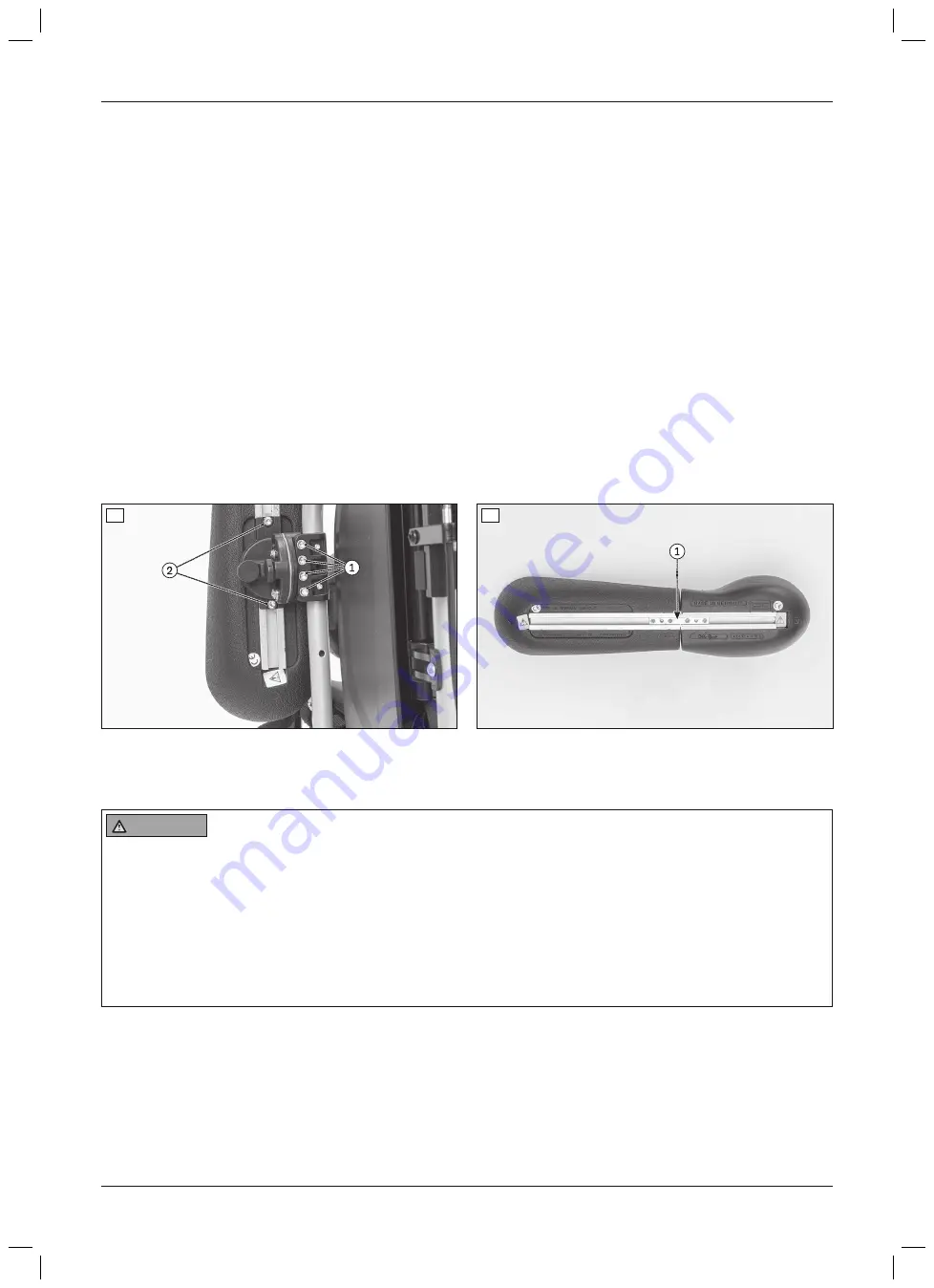
2) Mount the swivel unit on the tube of the side panel using the clamp bracket (see fig. 54, item 1).
The installation of the swivel unit is described in more detail in the supplied instructions for use – reference
number 647G411.
Installing the forearm supports on the swivel unit
1) Pre-install the forearm support/hand support using the connection piece (see fig. 55, item 1).
2) Mount the forearm support on the moveable part of the swivel unit (see fig. 54, item 2).
Installation on the swivel unit is described in more detail in the supplied instructions for use – reference number
647G411.
Adjusting the swivel unit with forearm support
Adjusting the swivel unit with forearm support is described in more detail in the supplied instructions for use (user).
54
55
6.12 Installing and adjusting frame options
6.12.1 Installing and adjusting the anti-tipper
WARNING
Incorrect installation of the anti-tipper/missing anti-tipper
Tipping over, falling of the user due to failure to observe the installation instructions and because of incorrect
adjustment
►
Depending upon the settings of the chassis, the centre of gravity, the back angle and the experience of the
user, the use of an anti-tipper may be necessary.
►
For a small wheelbase and a backrest that is tilted far back, an anti-tipper may need to be installed on both
sides, depending upon the user's experience.
►
Verify that the anti-tipper has been installed and adjusted properly. Find the appropriate position with the
assistance of a helper.
Installing the anti-tipper
1) Pull the end cap off the frame tube (see fig. 56).
2) Depress the rear spring button on the upper tube section of the anti-tipper (see fig. 57, item 1).
3) Slide the anti-tipper into the frame tube until the tripod spring snaps into place automatically (see fig. 57,
item 2).
24
Settings
Start M2S, Start M2


