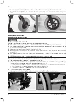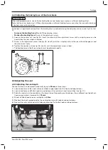
Changing the drive wheel position has the following effects:
Position of drive wheel
Effects
Move backwards (passive setting) •
Larger wheelbase
•
Larger turning circle
•
Greater stability of the wheelchair
•
Wheelchair is harder to tip backwards when crossing obstacles
•
Position recommended for inexperienced users
Move forwards (active setting)
•
Smaller wheelbase
•
Less load on caster wheels = greater manoeuvrability
•
Less stability of the wheelchair
•
Wheelchair is easier to tip backwards when crossing obstacles
INFORMATION: An anti-tipper should be installed if necessary.
•
Setting recommended only for experienced users
Start M4 XXL
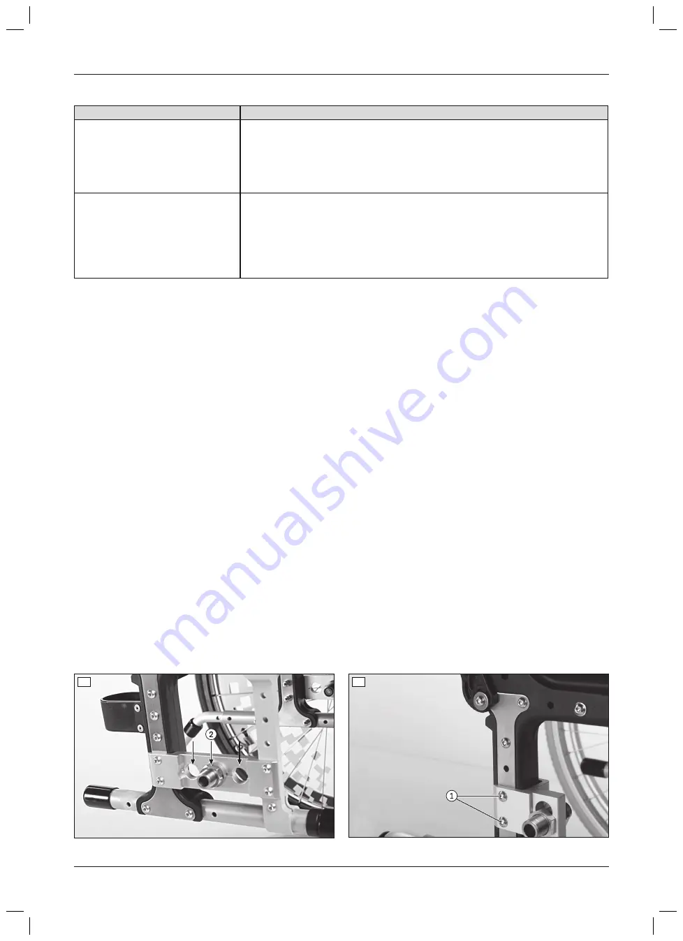
The drive wheel can be installed at three depth positions in the drive wheel adapter.
1) Remove the wheels.
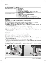
2) Loosen each hexagon nut (see fig. 1, item 2) from the fitting and remove the fitting towards the inside.
3) Slide the fitting back on in the desired position and tighten the hexagon nut slightly.
4)
If necessary:
The distance between the drive wheel and the side panel can be continuously adjusted by turn
ing the counter nut on the fitting.
5) Tighten each hexagon nut and the counter nut on both sides of the fitting to
50 Nm
.
INFORMATION: After adjustment, the distance of the left and right fittings to the side panel must be
the same.
6) Check the depth setting. Both sides must be positioned exactly the same. Readjust if necessary.
7)
If necessary:
Readjust the height and alignment of the caster attachment device (see Page 13) as well as the
brakes (see Page 14).
Start M6 Junior
The drive wheel can be installed using the drive wheel adapter at two depth positions.
1) Remove the wheels.
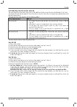
2) Remove both mounting screws on the drive wheel adapter (see fig. 2, item 1).
3) Turn the drive wheel adapters forwards or backwards to the desired position.
4) Insert the two mounting screws on the drive wheel adapter and tighten to
10 Nm
.
5)
If necessary:
The distance between the drive wheel and the side panel can be continuously adjusted by turn
ing the counter nut on the fitting.
6) Tighten each hexagon nut and the counter nut on both sides of the fitting to
50 Nm
.
INFORMATION: After adjustment, the distance of the left and right fittings to the side panel must be
the same.
7) Check the depth setting. Both sides must be positioned exactly the same. Readjust if necessary.
8)
If necessary:
Readjust the height and alignment of the caster attachment device (see Page 13) as well as the
brakes (see Page 14).
1
2
10
Settings
Start M4 XXL, Start M6 Junior


