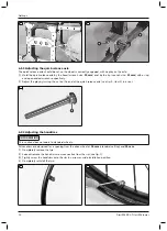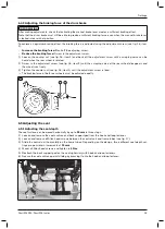
3) Tighten the Allen head screw to
6 Nm
.
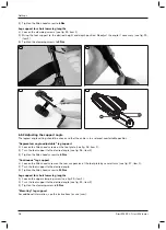
Leg support for short lower leg lengths
1) Loosen the clamping screws (see fig. 25, item 1).
2) Bring the foot support to the desired height and depth position. Readjust the angle if necessary (see fig. 25,
item 2).
3) Tighten the clamping screws to
9 Nm
.
22
23
24
25
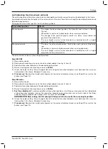
6.8.2 Adjusting the support angle
The legrest angle setting should be chosen so that the ankle is in a relaxed, comfortable position.
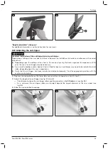
“Segmented, angle-adjustable” leg support
1) Loosen the Allen head screws on the foot plate (see fig. 26, item 1).
2) Turn the foot support to the desired angle (see fig. 26, item 2).
3) Tighten the Allen head screws to
6 Nm
.
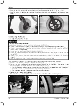
“Continuous” leg support
1) Loosen the Allen head screw on the rear suspension of the foot plate by several turns (see fig. 27, item 1).
2) Turn the foot support to the desired angle.
3) Tighten the Allen head screw to
10 Nm
.
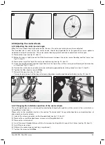
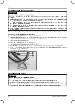
Leg support for short lower leg lengths
1) Loosen the upper clamping screw (see fig. 25, item 1).
2) Turn the foot support to the desired angle (see fig. 25, item 2).
3) Tighten the clamping screw to
9 Nm
.
“Elevating” leg support
For additional information, see the instructions for use (user).
18
Settings
Start M4 XXL, Start M6 Junior

