User manual for OTTO HEUSS universal stop motor PCB RM-2
Otto Heuss GmbH
Page
4
of
8
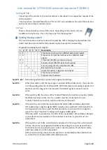
The white connectors are designed for cables up to 1.5mm².
The designation of the connections can be read when the white plugs are removed.
The four cables of the motor AN-SPULE/COM/COM/AB-SPULE are connected to the
"motor"
connector at the corresponding terminals. [ON-Coil/COM/COM/OFF-Coil]
At the Setter connector, up to four cables are connected to the associated terminals for Setter
control.
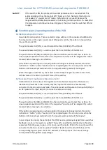
The following control lines are provided:
Kontakt [Contact]
Status feedback to the setter in case of an el./mechanical dual stop action. For this
purpose, a switch must be connected to the two "Schalter"[Switch] connection points,
which are located at the bottom longitudinally on the edge of the board. If the two
connections are connected to each other by closing a switch, a positive signal in
operating voltage is output at the "Kontakt" [Contact] connection.
Attention:
No external voltage must be applied to this connection.
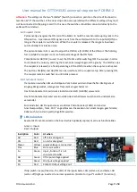
AN [ON]
Connection for the signal to switch on the motor from the setter or stop switch (RS,
RzO). Input optionally positive or negative switching, adjustable with dip-switch 5.
When used as an electrical slider motor a permanent signal is required, if this signal
drops off, the magnet is switched off again. When used as el. / mechanical dual stop
action a momentary signal (pulse) is required.
AB [OFF]
Connection for the signal to switch off the motor, this is only used for the
electrical/mechanical dual stop action version,
otherwise no cable connection
required
. Input can be set to either positive or negative switching with dip-switch 5.
As this input is only used with an electric/mechanical dual stop action, a momentary
signal (pulse) is always required here.
Funktion [Function]
Connector for the signal to switch on various special functions such as
“stop freeze”. This input always need a negative signal.
Attention:
No positive voltage (+1 to 28V) must be applied to this connection from an external source.
Schalter [Switch]
2-pole connection for a closing switch at the bottom longitudinal edge of the board
when used with el./mechanical dual stop action. If these two contacts are connected
to each other, a signal in operating voltage is given out at "Kontakt".
Attention:
The voltage at the two connection points "Schalter"[Switch] on the side of the board is
internally less than 6V which is switched by the switch. If the switches of the dual stop action are
operated with an external voltage, they must not be connected to the PCB! In this case the switches
should be connected directly to the setter without detour via the board.
Trem.Poti.[Tremulant Potentiometer]
3-
pin connector for a 10kΩ potentiomet
er, top longitudinal on
the edge of the board when used with a tremulant motor. This potentiometer is used
to control the speed of the tremulant. The center contact of the potentiometer
corresponds to the center contact on the board.


