OUMAN EH-203
DIGITAL INPUTS 1, 2, 3
OUMAN EH-203
Directions for entering the
maintenance mode are on page 21.
EH-203 has three digital inputs. A digital input can be connected
to contact information or pulse information. Contact information can be used to
receive an alarm, e.g., blower overcurrent protection alarm. Alarms can be labelled
using the text editor according to their cause. Alarms can be transferred to, e.g., A
GSM phone as text messages. Pulse information can be read, e.g., from a district
heating energy meter or water meter.
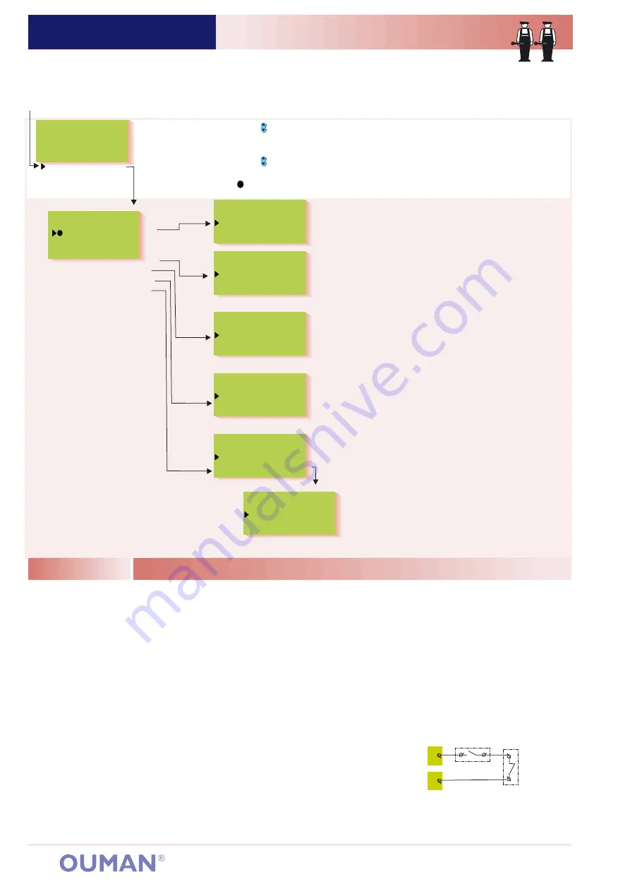
Dig1 selection:
Alarm Dig 1
Exhaust ½ pwr
Home/away
PumpI running
DH Energy
MWh
DH Water
m3
Watr consmp. m3
Special mainten.
Rstore settings
Settings
Meas. 6 setting
Dig1 selection
Dig2 selection
Dig3 selection
LON initializ.
Press the
button to move the cursor to”Dig 1, Dig 2 or Dig 3 selection”.
Press
Press the
button to move the cursor to indicate which information
has been connected to the Dig channel in question. Press
The
character indicates the selection made.
OK
OK
.
.
32
Alarm use:
Alarm switch information. When the switch is
closed, an alarm goes off. You can use the text editor to label
the alarm, e.g., Order oil! (see p. 8). In the event of an alarm,
the regulator sounds the alarm and indicates on the display
from which digital input the alarm came from. Transferring the
alarm to a GSM phone (see p. 36, 37).
Pulse information from the district heating energy
meter:
OK
OK
Pulse information from the district heating water meter:
OK
OK
Pulse information from the facility's water meter:
OK
OK
.
.
.
.
.
.
Press
Set the number of kWh equivalent to
one pulse and press
District heating energy
consumption (MWh) and the momentary (5 min. follow-up
period) district heating power consumption (kW) can be
seen on the regulator's measurements display.
Press
Set the number of liters equivalent to one pulse
and press
District heating water consumption (DH m3)
and the momentary district heating water consumption (Inst.
l/s) can be seen on the regulator's measurements display.
Press
Set the number of liters equivalent to one pulse and
press
The facility's water consumption (Water m3) can
be seen on the regulator's measurements display.
Exhaust ½pwr
Home/away
Pump 1(2) running:
Exhaust fan ½ speed information. When the switch is closed the exhaust fan is at ½ speed.
Away switch information. (switch closed, H1/H2 reduced temperature mode is on).
In speed controlled pumps, pump indication is taken from alarm contacts or from a
separate overcurrent protection in the input current circuit. In the event of an alarm the contact closes. If the
alarm is given when the alarm contact closes, the alarm is acknowledged from a separate switch. The alarm
may stop sounding after a power failure. Contact information for constant speed pumps is taken from the
pump's temperature relay. When the contact is closed the pump does not run. The controller then gives an
alarm and starts up the other pump (if the alternate pump is in use).
The information is used to lower the heat when the exhaust fan is at ½ speed. The amount of the drop is
given in special maintenance settings. (see p. 27, ½ exhst )
Pump running mode information is taken from a separate potential free closing contact in the
input current circuit. (The pump runs when the contact is closed). Speed controlled pumps usually do not have
their own running information contact. If a speed controlled pump is controlled by cutting the supply voltage
Overcurrent protection:
Running mode:
Explanation:
On the display:
Pump1(2) running indication:
The purpose of this function
is check that the pump is in operating condition. Select
whether to inspect pump running from running mode
information or from information received from overflow
protection.
Inspection of hot water network for leaks:
OK.
OK.
Press
Set the length of the control period. Press
If in
a 24 hour period there is no time period with no
consumption for the length of the control period the
controller gives a consumption alarm indicating
continuous hot water consumption. With the setting at
0 (factory setting) the function is not in use. The setting
range is 0…99 minutes.
21
22
Dig 1
Speed controlled
pump's own
alarm contact
Closing running
information
ConsumptAlarm
Name change
Alarm Dig 1
Give new label
Pump indication
OverCurrProt
Running mode
DH Energy set.
Pulse =
kWh
0.0
DH watr metr set
Pulse =
l
0
Watr consm set
pulse =
l
0
ConsumptionAlrm
ConsumptionAlrm
CtrlPeriod
min
0
If in a 24 hour period there is no pulseless time period of the length of the control period, the controller
gives a leakage alarm. The alarm is acknowledged locally from the controller. The alarm can also be
automatically acknowledged if there is a pulseles control period during the next 24 hour period. This
function can be used to discern moderate sized leaks, e.g., a leaking toilet.
(not recommended) the pump's own alarm contact can be connected
as an opening contact to the input current circuit as a series with the
potential free contact. (see diagram to the right). Compare the running
information and control. If control and running information are not in
the same mode the controller gives a contradiction alarm if the
contradicting situation has lasted for 10s. In a contradicting situation
the controller keeps controlling the pump. When the contradiction
ends the alarm is turned off.


