Last Update: 2011-June INSTRUCTION MANUAL FOR THERMOSYPHONIC SYSTEMS
18/35
©TANSUG MAKİNA LTD. 2008
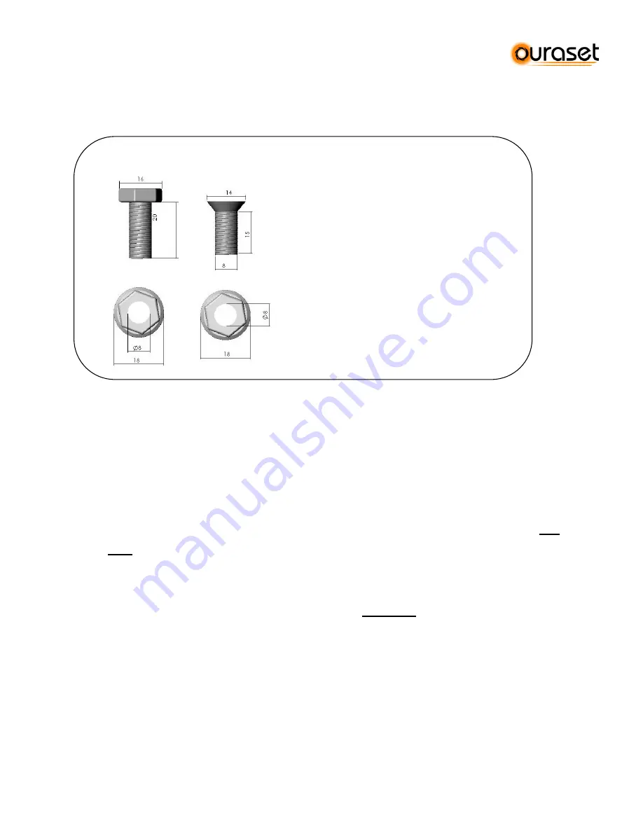
6.3 Description of screws that are used in the mounting of the stands.
You will use two kinds of screws that will be sent with your structure.
6.4 Assembly of Thermosyphonic Flat Roof Stand (TFR45)
6.4.1
Connect the
base frame
(A) with the tank support beds (F6), then the support beds (F6)
to the vertical frame (B) and side frame (C). Use side diagonal (E) to complete one leg of
the structure. Measure the dimensions illustrated at Figure A.
6.4.2
Put together the second leg of the structure in the same way described at step 4.1.1.
6.4.3
Use back diagonals (E) to connect the two legs of the structure together. Measure
880
mm.
between the center of tank beds for structure type TFR45-1 for systems 121-151-
191 when connecting the back diagonals. (See Figure A). Use the holes on the vertical
frames (B) that correspond to this distance between the two legs.
6.4.4
The distance between the center of tank beds is
1260 mm.
for structure type TFR45-2 for
systems 192-302. (See Figure B)
6.4.5
Install the aluminum panel frames on the base frames (A) , first the bottom aluminum
frame(D) to the first hole of the base frame from the bottom. Then put the top aluminium
panel frame (D) on the corresponding hole on the base frame that measures 1950 mm.
Remember that solar panel will be located between these two aluminium frames.
6.4.6
Screw the tank wind belt (G) on the tank beds (F) from the front. Screw the belts from the
back of the stand only after you have placed the tank on the tank beds, after when you
have finished all steps of the installation of the structure.
TYPE 2 TYPE 3
TYPE 2 :
Standard Structure
Assembly Screws
TYPE 3 :
Flat Head Screws- used for
connection of tank support
bed to wind belt


