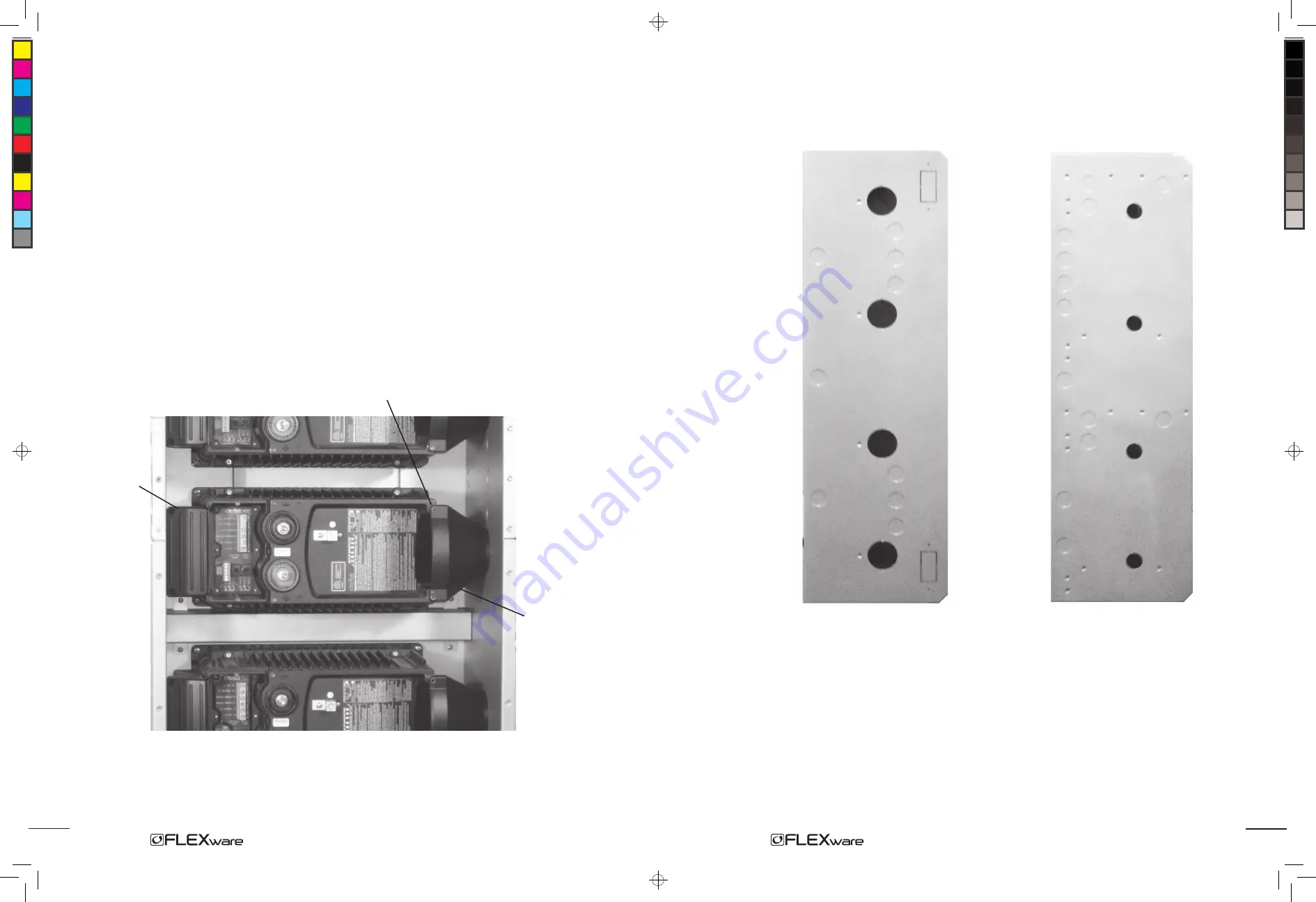
Figure 10:
ACAs (left) and DCAs (right) in place
11
• Line up either the ACA or DCA (conduit adapters) on its respective side of an FX, starting at
the top.
• To attach a DCA, line up its two screw holes with the upper and lower right DCC screw holes.
• When lined up, loosely install the upper screw to hold the DCA in place (screw can be removed
later when the DCC is installed).
• Slide the DC chassis over snug against the DCA (the screw slots in each chassis are oval-shaped
to allow for movement) so the DCA lines up with the conduit adapter hole on the chassis.
• Install the plastic bushing in this hole (see Figure 11).
• Install the remaining DCA(s) in this same manner. After inserting the bushing into the top DCA,
the remaining DCA(s) will line up and the other bushings can be installed.
• With all the DCA’s aligned with the DC chassis and the bushings installed, tighten the DC chassis
screws against the FW-MP.
Each ACA fits against the AC chassis.
A single screw holds the DCA Conduit Adapter in place.
Slide the DC chassis against each DCA to line it up with
the plastic bushing.
ACA
DCA
Installation of the AC Chassis and DC Chassis
After the FXs are installed, mount the AC chassis and the DC chassis in either order.
Figure 6:
It is easier to remove the appropriate side knockouts from both the AC and DC chassis
before installing either of them. If needed, the back knockouts must be removed before installation.
8
1000 Manual.indd, Spread 11 of 12 - Pages (14, 11) 11/22/06 11:07 AM


