background image

3

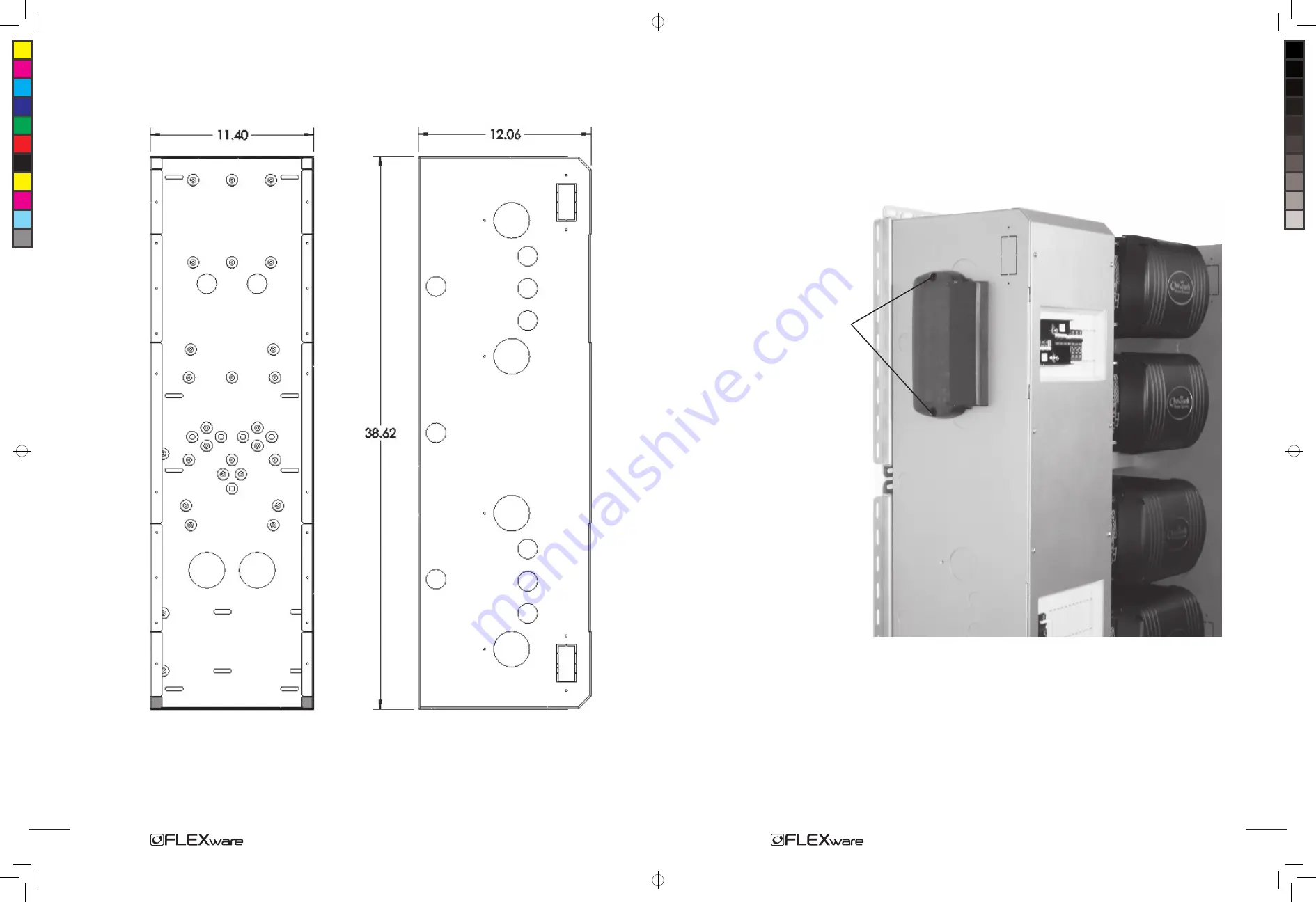
Figure 2:

  Front View                                                                                   Side View

Knockouts and Dimensions

Figure 14:

 OutBack HUB

Installing an OutBack HUB

An OutBack HUB allows the FX Series Inverter/Chargers, MX60 Charge Controllers, and MATE  
to communicate with each other. It attaches (see arrows in Figure 14) to the outside of the 
FW1000-AC (hardware included with the HUB).

HUB connection

16

1000 Manual.indd, Spread 6 of 12 - Pages (6, 19) 11/22/06 11:07 AM 

Summary of Contents for FLEXware 1000

Page 1: ...ña 34 600 843 845 19009 62nd Avenue NE Arlington WA USA 1 360 435 6030 www outbackpower com 900 0062 1 1000 User s Guide Includes Mounting Installation and Product Registration 1000 Manual indd Spread 1 of 12 Pages 24 1 11 22 06 11 07 AM ...

Page 2: ...06 1 0 Contact Information OutBack Power Systems 19009 62nd Ave NE Arlington WA 98223 Phone 360 435 6030 Fax 360 435 6019 www outbackpower com Product Registration Please take a moment to register and provide us with some important information Send to OutBack Power Systems 19009 62nd Avenue NE Arlington WA 98223 USA Name Address _____________________________________________________________________...

Page 3: ...ive battery conductor should be bonded to the ground ing system at one and only one point in the DC system All installations should comply with all national and local codes and ordinances System grounding as required by the National Electric Code ANSI NFPA 70 1996 is the responsibility of the system installer The equipment ground on FLEXware1000 is marked with this symbol FLEXware is designed for ...

Page 4: ...esired AC and DC disconnects FLEXware 500 which supports up to two FXs and two MX Charge Controllers accommodating both split phase and or higher power output as needed FLEXware 1000 accommodates up to four FXs and four MX Charge Controllers Please Note Both the FLEXware 500 and the FLEXware 1000 power systems provide locations for FW X240 Auto Transformers multiple DC shunts and other essential c...

Page 5: ...t HUB AC Breakers FW X240 Breaker MX60s DC Breakers Wiring Raceway PV and Bat breakers FW1000 DC Figure 1 FLEXware 1000 System Getting to Know FLEXware 1000 FW MP ACA FX with DCC DCA 2 1000 Manual indd Spread 5 of 12 Pages 20 5 11 22 06 11 07 AM ...

Page 6: ...k HUB An OutBack HUB allows the FX Series Inverter Chargers MX60 Charge Controllers and MATE to communicate with each other It attaches see arrows in Figure 14 to the outside of the FW1000 AC hardware included with the HUB HUB connection 16 1000 Manual indd Spread 6 of 12 Pages 6 19 11 22 06 11 07 AM ...

Page 7: ... Breaker IOB Kit bus bars and DC current shunts as required per specific installation DC and AC ground fault protection Some systems will work optimally with a FW X240 Auto Transformer installed Note Be sure you have all the parts required for your intended system installation As every installation is different consult with your dealer or installer for further information FLEXware 1000 Parts List ...

Page 8: ...designed for the FLEXware 1000 installation This manual illustrates such an installation OutBack does not endorse other installation methods and therefore cannot recommend fasteners or other means of attachment due to the variety of installations possible in the field Please see the FLEXware Mounting Plate Instructions for further information In addition to installing the AC and DC chassis a typic...

Page 9: ...tions for directly attaching an MX Charge Controller are shown below Figure 4 Two mounting plates installed Note Check that both FW MPs are level as per the FLEXware Mounting Plate Installation Manual If space is restricted the FW MPs can be installed vertically With the Mounting Plate and the hanging screws for the FX Series Inverter Chargers installed install the FXs Start with the top FX Hang t...

Page 10: ...against the ACAs after the ACA installations Press a 1 plastic bushing from inside the AC chassis out to the ACA through each previously removed knockout sliding the AC chassis against the ACAs until snug With all the ACA s aligned with the AC chassis and the bushings installed tighten the AC chassis screws against the FW MP With both the AC chassis and DC chassis installed the breaker brackets AC...

Page 11: ...s in this same manner After inserting the bushing into the top DCA the remaining DCA s will line up and the other bushings can be installed With all the DCA s aligned with the DC chassis and the bushings installed tighten the DC chassis screws against the FW MP Each ACA fits against the AC chassis A single screw holds the DCA Conduit Adapter in place Slide the DC chassis against each DCA to line i...

Page 12: ... into the holes shownin Figure 7 tightening only enough to keep the chassis in place AC side DC side Figure 7 Chassis Mounting Holes AC chassis Mounting Holes DC chassis Mounting Holes Figure 8 AC and DC Chassis mounted With each chassis loosely mounted the AC Conduit Adapter ACA and DC Conduit Adapter DCA are installed on the FX Remove the clear plastic AC cover and AC Conduit Plate from each FX ...

Page 13: ... into the holes shownin Figure 7 tightening only enough to keep the chassis in place AC side DC side Figure 7 Chassis Mounting Holes AC chassis Mounting Holes DC chassis Mounting Holes Figure 8 AC and DC Chassis mounted With each chassis loosely mounted the AC Conduit Adapter ACA and DC Conduit Adapter DCA are installed on the FX Remove the clear plastic AC cover and AC Conduit Plate from each FX ...

Page 14: ...s in this same manner After inserting the bushing into the top DCA the remaining DCA s will line up and the other bushings can be installed With all the DCA s aligned with the DC chassis and the bushings installed tighten the DC chassis screws against the FW MP Each ACA fits against the AC chassis A single screw holds the DCA Conduit Adapter in place Slide the DC chassis against each DCA to line i...

Page 15: ...against the ACAs after the ACA installations Press a 1 plastic bushing from inside the AC chassis out to the ACA through each previously removed knockout sliding the AC chassis against the ACAs until snug With all the ACA s aligned with the AC chassis and the bushings installed tighten the AC chassis screws against the FW MP With both the AC chassis and DC chassis installed the breaker brackets AC...

Page 16: ...tions for directly attaching an MX Charge Controller are shown below Figure 4 Two mounting plates installed Note Check that both FW MPs are level as per the FLEXware Mounting Plate Installation Manual If space is restricted the FW MPs can be installed vertically With the Mounting Plate and the hanging screws for the FX Series Inverter Chargers installed install the FXs Start with the top FX Hang t...

Page 17: ...designed for the FLEXware 1000 installation This manual illustrates such an installation OutBack does not endorse other installation methods and therefore cannot recommend fasteners or other means of attachment due to the variety of installations possible in the field Please see the FLEXware Mounting Plate Instructions for further information In addition to installing the AC and DC chassis a typic...

Page 18: ... Breaker IOB Kit bus bars and DC current shunts as required per specific installation DC and AC ground fault protection Some systems will work optimally with a FW X240 Auto Transformer installed Note Be sure you have all the parts required for your intended system installation As every installation is different consult with your dealer or installer for further information FLEXware 1000 Parts List ...

Page 19: ...k HUB An OutBack HUB allows the FX Series Inverter Chargers MX60 Charge Controllers and MATE to communicate with each other It attaches see arrows in Figure 14 to the outside of the FW1000 AC hardware included with the HUB HUB connection 16 1000 Manual indd Spread 6 of 12 Pages 6 19 11 22 06 11 07 AM ...

Page 20: ...t HUB AC Breakers FW X240 Breaker MX60s DC Breakers Wiring Raceway PV and Bat breakers FW1000 DC Figure 1 FLEXware 1000 System Getting to Know FLEXware 1000 FW MP ACA FX with DCC DCA 2 1000 Manual indd Spread 5 of 12 Pages 20 5 11 22 06 11 07 AM ...

Page 21: ...esired AC and DC disconnects FLEXware 500 which supports up to two FXs and two MX Charge Controllers accommodating both split phase and or higher power output as needed FLEXware 1000 accommodates up to four FXs and four MX Charge Controllers Please Note Both the FLEXware 500 and the FLEXware 1000 power systems provide locations for FW X240 Auto Transformers multiple DC shunts and other essential c...

Page 22: ...ive battery conductor should be bonded to the ground ing system at one and only one point in the DC system All installations should comply with all national and local codes and ordinances System grounding as required by the National Electric Code ANSI NFPA 70 1996 is the responsibility of the system installer The equipment ground on FLEXware1000 is marked with this symbol FLEXware is designed for ...

Page 23: ...06 1 0 Contact Information OutBack Power Systems 19009 62nd Ave NE Arlington WA 98223 Phone 360 435 6030 Fax 360 435 6019 www outbackpower com Product Registration Please take a moment to register and provide us with some important information Send to OutBack Power Systems 19009 62nd Avenue NE Arlington WA 98223 USA Name Address _____________________________________________________________________...

Page 24: ...ña 34 600 843 845 19009 62nd Avenue NE Arlington WA USA 1 360 435 6030 www outbackpower com 900 0062 1 1000 User s Guide Includes Mounting Installation and Product Registration 1000 Manual indd Spread 1 of 12 Pages 24 1 11 22 06 11 07 AM ...

Reviews: