13
HGI-31 : 1-23-2018
www.outdoorrooms.com
•
The installer must mechanically attach the
marking supplied with the gas fireplace insert
to the inside of the firebox of the fireplace into
which the gas fireplace insert in installed
•
Cutting any sheet-metal parts of the fireplace in
which the gas fireplace insert is to be installed is
prohibited.
•
If the factory-built fireplace has no gas access
hole(s) provided, an access hole of 1.5 in (38.1
mm) or less may be drilled through the lower
sides or bottom of the firebox in a proper
workmanship like manner. This access hole
must be plugged with non-combustible
insulation after gas supply line has been
installed.
•
The fireplace flue damper can be fully blocked
open or removed for installation of the gas
fireplace insert.
•
The fireplace and fireplace chimney must
be clean and in good working order and
constructed of non-combustible materials.
•
Refractory, glass doors, screen rails, screen
mesh, and log grates can be removed from
the fireplace before installing the gas fireplace
insert.
•
Trim panels or surrounds shall not seal
ventilation openings in the fireplace.
•
Ensure that chimney clean outs fit properly.
•
Smoke shelves, shields, and baffles may be
removed if attached by mechanical fasteners.
•
Ensure a tight connection is made between the
gas insert flue collar and fireplace chimney.
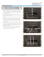
5. Slowly lower your rope down the chimney.
After the rope is inside the firebox, the installer
on the rooftop feeds the flex vent down the
chimney while a second person guides the
pipe through the chimney by pulling on the
rope from the interior of the house.
6.
After both flex vents are in place, attach the
cap with the end you marked exhaust to the
exhaust terminal of the roof cap. The roof cap
can now be secured in place.
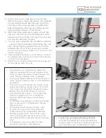
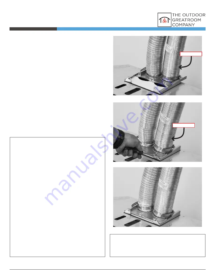
7. You can now complete the installation indoors
- connect the Termination Plate inside the unit
first connecting the exhaust flex vent to the
exhaust side. (Img. 5-6)
(clamps are provided
with vent kit and require either a 1/4” wrench or flat-
head screwdriver)
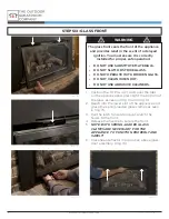
8.
Press fiberglass insulation around the two vents, at
the damper level, to prevent cold air from entering
or hot air from escaping.
9. Attach the Termination Plate to the unit using two
(2) provided screws. (Img. 6)
(Img. 7)
(Img. 6)
(Img. 5)
EXHAUST
EXHAUST

