background image

outdoorrooms.com

11

E. FINISHING (MANTELS AND SPECIAL CASES)

WARNING

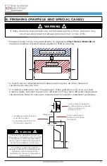
If these clearance requirements are not followed exactly, a fire or explosion may 

result casuing property damage, personal injury or loss of life.

!

!

1”

1”

8”

6”

8”

6”

If installing a television over the appliance, these guidelines will serve as a best 

practice guide, but each television is different and may have different temperature 

requirements. Refer to television manufacturer for specific installation guidelines.

A hearth can be installed below fireplace opening, but all other clearance

requirements must be met.

Alcove must be designed 

so that television is recesed 

from front face by a

minimum of 4”.

Alcove must begin a 

minimum of 8” above 

the mantel.

Installations with a television 

must use a mantel.

A minimum depth of 8” for 

the mantel is required.

Minimum

NO MANTEL

MANTEL CAN BE MOUNTED

Mantels should not be mounted directly to appliance. 

ONLY NON-COMBUSIBLE


mantels should be installed above appliance firebox opening.

4”

WARNING

These are only guidelines and do not

ensure that an installation will not excede 

manufacturer maximum temperatures. 

Areas should be tested for tempurature 

before final installation of television.

The Outdoor Greatroom Company

accepts no liability for installations with 

televisions that do not meet the

manufacturers maximum temperature 

requirements.

!

!

1”

Minimum

Summary of Contents for RSTL

Page 1: ...Installation Instructions for All Ready to Finish See Through and Single Sided Outdoor Fireplaces RSTL RLFP Ready to Finish Outdoor Fireplace outdoorrooms com...

Page 2: ...About Your Fireplace 2 a Required Tools outdoorrooms com 42515 REV B 10 29 21 1 b Included With Your Fireplace 2 Assembly Instructions a Unpacking 3 Setting Up Your Burner b Natural Gas Connections c...

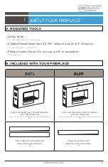
Page 3: ...ssembly 1 ABOUT YOUR FIREPLACE Set of Glass Wind Guards and Glass Guard Clip Hardware 1 Single Glass Panel and Glass Guard Clip Hardware 1 Fully Assembled See Through Fireplace with CFP DSI Burner See...

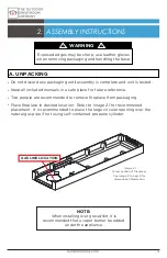
Page 4: ...Image 2 1 for recommened placement It is recommended to place the large circular opening over the natural gas pipe if not using self contained propane cylinder Exposed edges may be sharp use leather...

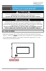
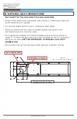
Page 5: ...beginning burner hookups or using the device DO NOT USE TEFLON TAPE OR PIPE DOPE ON FLARE FITTINGS 3 IMPORTANT Please consult your Crystal Fire Plus instruction manual for detailed instructions and i...

Page 6: ...opening in bottom of base See Crystal Fire Plus instructions for burner installation All gas connections were completed at the factory Performing a leak test on all connections is required It is recom...

Page 7: ...move bolts holding access plate to pan as shown in Image 3 4 Carefully lift up both access plates and tilt inwards to remove Take care not to scratch stainless steel interior side panels Tighten all c...

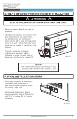
Page 8: ...replace in large circular hole in base pan As shown in Image 3 5 E SELF CONTAINED PROPANE CYLINDER INSTALLATION HAND TIGHTEN DO NOT USE A WRENCH FOR THIS CONNECTION ATTENTION F FINAL INSTALLATION STEP...

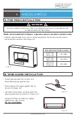
Page 9: ...h fireplace a seperate order is needed to obtain media B WIND GUARD INSTALLATION Install glass guard clip screws into backside of glass guard clips Place spacer into glass guard clip as shown in Image...

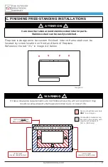
Page 10: ...actly a fire or explosion may result casuing property damage personal injury or loss of life Image 4 4 x x x x ATTENTION Care must be taken around stainless steel interior parts Stainless steel can be...

Page 11: ...nce on sides for see through units Vents can be moved to front or near of appliance to provide for required air movement NOTE Standoff kits are available for purchase to assist in the framing process...

Page 12: ...cove must be designed so that television is recesed from front face by a minimum of 4 Alcove must begin a minimum of 8 above the mantel Installations with a television must use a mantel A minimum dept...

Page 13: ...self contained propane cylinder slowly open cylinder valve Turn control switch to ON position A 1 2 second delay will occur while control module runs diagnostics Sparking will then occur at the ignit...

Page 14: ...GNITION position Fully depress control knob and hold for 3 5 seconds See Image 6 3 Burner should ignite and continue to operate when control knob is released If burner does not light or remain lit aft...

Page 15: ...ding lighting and operating instructions safety information and proper tightening of connections with two wrenches DO NOT ATTEMPT TO INSTALL CRYSTAL FIRE PLUS BURNER WITHOUT FIRST CONSULTING THE CRYST...

Page 16: ...was made with pride in the USA Warranty Outdoor fireplaces are covered under a 1 year manufacturer s warranty Please visit http www outdoorrooms com product registration to register your product 1440...

Reviews: