background image

www.desatech.com

122139-01A

7

ASSEMbLy

Continued

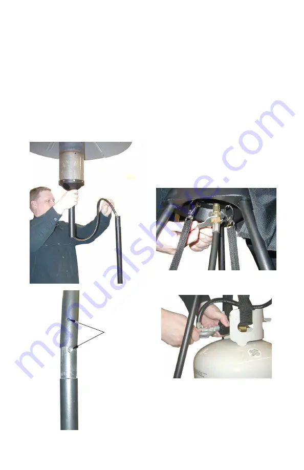
Figure 10 - Burner Installation

Figure 11 - Attaching Regulator Hose to 

Burner Fuel Line

10. Inspect length of gas hose on bottom of 

burner assembly for any cracks, cut, holes 

or excessive wear. Do not use heater if 
hose is damaged.

11. Sliding hose into upper pole, install burner 

and reflector assembly to base (see Fig

-

ure 10). 

12. Align hole in burner assembly pole with 

hole in upper pole (see Figure 10). Secure 

burner  assembly  to  upper  pole  using  a 

wing  bolt.  Be  sure  to  tighten  wing  nut 

completely.

Align Hole 

in Burner 

Assembly 
With Hole in 
Upper Pole

Figure 12 - Connecting Regulator to 

Propane/LP Gas Tank

13. Lift  tank  cover.  Install  regulator  hose  to 

burner fuel line using wrenches provided 

in hardware bag (see Figure 11).

14. Securely connect regulator to propane/LP 

gas cylinder (see Figure 12). When con

-

necting regulator assembly to tank valve, 

hand tighten nut clockwise to a positive 
stop. 

dO NOT use a wrench to tighten

Use of a wrench may damage quick clos

-

ing coupling nut and result in a hazardous 

condition.

15. Open cylinder valve. Apply a noncorrosive 

leak  detection  fluid  to  connections  at 

regulator. Bubbles forming show a leak.

16. If leaks exist, turn off propane/LP cylinder 

valve.  Disconnect  leaking  connection. 
Check and clean connection. Reconnect 
regulator and leak check again. 

17. If no leaks are present, pull cover down 

over tank and legs. Unit is now ready to 
light.

Summary of Contents for Heat-N-Glo TD120A

Page 1: ...g or servicing heater Improper use of heater can cause serious injury Keep this manual for future reference WARNING For outdoor use only FOR YOUR SAFETY Do not store or use gasoline or other flammable...

Page 2: ...ecifications Rating 21 000 Btu hr 6 15 kW Type of Gas Propane LP Only Gas Supply Pressure to regulator Maximum 150 psi 1034 2 kPa Minimum 5 psi 34 5 kPa Gas Supply Pressure Regulator out 11 W C 2 74 k...

Page 3: ...e assembly listed on parts list before using heater 9 This heater is for OUTDOOR USE ONLY even so make sure that there is ample fresh air ventilation Do not use in build ings garages or other enclosed...

Page 4: ...person More frequent cleaning may be required as necessary It is imperative that controlcompartments burnersand circulating air passageways of the heater be kept clean CAUTION The gas pressure regulat...

Page 5: ...er legs as shown in Figure 3 Be sure to tighten wing bolt after installation Figure 2 Installing Lower Legs into Upper Poles Figure 3 Installing Feet to Lower Poles Figure 4 Attaching Tank Straps Push...

Page 6: ...bolts as shown in Figure 8 9 Install reflector over post on top of burner assembly Install reflector cap over post Attach reflector and reflector cap using large wing nuts see Figure 9 Figure 7 Tank...

Page 7: ...ting Regulator to Propane LP Gas Tank 13 Lift tank cover Install regulator hose to burner fuel line using wrenches provided in hardware bag see Figure 11 14 Securely connect regulator to propane LP ga...

Page 8: ...nob and Ignitor Button Control Knob Ignitor Button Match Hole TO LIGHT 1 Open main gas supply valve on propane cylinder 2 Turn control knob on heater to the ON position Press for 3 seconds While press...

Page 9: ...least 45 minutes for heater to cool down after using 2 Disassemble heater in reverse order that it was assembled 3 Place all hardware in provided tool bag 4 Store unit in bag until ready to use again...

Page 10: ...www desatech com 122139 01A 10 Parts Model TD120A 22 21 20 19 11 12 10 9 5 4 3 1 2 15 14 13 16 17 18 7 6 8...

Page 11: ...Tube 1 12 121025 02 Burner Base 1 13 V01 034 Control Knob 1 14 122413 01 Fitting Nut 1 15 121028 01 Igniter 1 16 121029 02 Bulkhead Fitting 1 17 121030 02 LP Gas Hose Assembly 1 18 121031 02 Burner Po...

Page 12: ...for thirty 30 days from the date of first purchase when operated and maintained in accordance with the manufacturer s instructions These warranties are extended only to the original retail purchaser w...

Page 13: ...s de ensamblar encender o dar servicio al calentador El uso inadecuado del calentador puede causar lesiones gra ves Conserve este manual para referencias futuras PARA SU SEGURIDAD No guarde ni utilice...

Page 14: ...ridad ADVERTENCIA esteproducto contieney ogeneraqu micosque el Estado de California reconoce que causan c ncer defectos de nacimientouotrosda osrelacio nados con la reproducci n ADVERTENCIA no usar en...

Page 15: ...e el tanque de combustible y el piso es de 5 cm 2 7 Uses loelensamblajedereguladoryman guera que se incluye con el calentador Seguridad Continuaci n 8 Inspeccione el ensamblaje de la man guera antes d...

Page 16: ...encuentrenen el rea del calentador La ropa u otros materiales infla mables no se deben colgar en el calentador ni colocarse sobre ste o cerca de l Seguridad Continuaci n Unapersonadeserviciocapaci tad...

Page 17: ...r como se muestra en la figura 1 Compruebe que los tubos roscados se asienten totalmente en el interior de la base 2 Instale las patas inferiores presionando el seguro e insert ndolo en el tubo superi...

Page 18: ...tanque en la base consulte la figura 5 6 Instale la correa de seguridad en el tanque y ajuste las correas en las patas seg n se muestra en la figura 6 7 Instale la cubierta del tanque consulte la fig...

Page 19: ...dici n de peligro 15 Abra la v lvula del cilindro Aplique l qui do no corrosivo para detectar fugas en el regulador La formaci n de burbujas indicar una fuga 16 Si hay alguna fuga cierre la v lvula de...

Page 20: ...cen dido Mant ngala presionada durante 3 segundos Mientras presiona la perilla de control oprima varias veces el bot n rojo del encendedor hasta encender el quemador es posible que deba oprimir el bot...

Page 21: ...lestias f sicas No hay humo ni holl n dentro o fuera del calentador Si el calentador no se enciende o permane ce encendido comun quese con un t cnico de servicio capacitado Las listas de piezas y el d...

Page 22: ...Piezas Modelo TD120A 22 21 20 19 11 12 10 9 5 4 3 1 2 15 14 13 16 17 18 7 6 8 www desatech com 120948 01A 10...

Page 23: ...se 1 20 121034 01 Patas superiores roscadas 3 21 121035 01 Patas inferiores 3 22 121036 01 Pie de metal 3 Partes que no se muestran 121037 01 Bolsa de ferreter a 1 121038 01 Perno para tuerca de marip...

Page 24: ...DE CUALQUIER OTRA GARANT A YA SEA EXPRESA O IMPL CITA INCLUYENDO GARANT AS DE COMERCIABILIDAD Y APTITUD PARA UN PROP SITO EN PARTICULAR DESA Heating LLC no asume responsabilidad por da os consecuentes...

Reviews: