background image

9

Outdoor Lifestyles by Hearth & Home Technologies  •  Twilight-II-B Installation Manual  •  2108-970 Rev. H  •  5/14

B.  Clearances to Combustibles

When selecting a location for the appliance it is important 

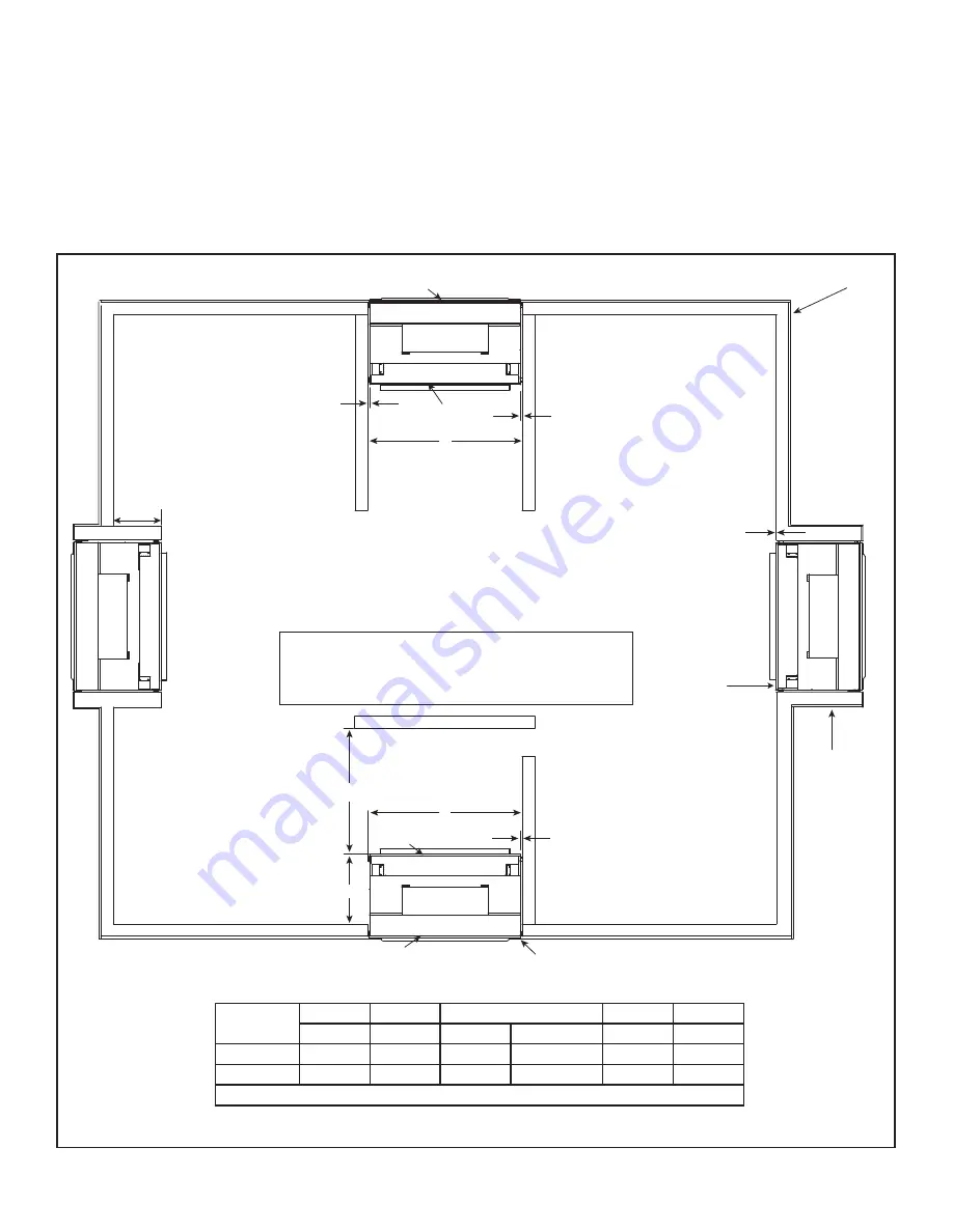
to consider the required clearances to walls (see Figure 
3.2).

WARNING! Risk of Fire or Burns! 

Provide adequate 

clearance around air openings and for service access. 
Due to high temperatures, the appliance should be lo-
cated out of traf

fi

 c and away from furniture and draperies.

Figure 3.2  Appliance Locations

NOTICE: 

Illustrations re

fl

 ect typical installations and are 

FOR DESIGN PURPOSES ONLY. Illustrations/diagrams 
are not drawn to scale. Actual installation may vary due to 
individual design preference.

WARNING!  Risk of Fire! 

The exterior side of the TWI-

LIGHT-II-B 

CANNOT 

be recessed into the framing.

GLASS

EXTERIOR INSULATED ENVELOPE

GLASS

A

B

B

D

C* = 24 INCH (MAX.)

GLASS

FLUSH TO EXTERIOR INSULATED ENVELOPE

GLASS

E

C*

NOTE:  Appliance may be installed flush on exterior, interior or 
anywhere in between.   Any projection of the appliance interior 
or exterior must have a properly constructed chase surround-
ing the appliance.  The exterior must have proper insulating, 
flashing and finishing to ensure an insulated envelope.

FLUSH 
TO INTERIOR

PROJECTION

C* = 0 INCH (MIN.)

WARNING!  Risk of Fire! The exterior side of the TWILIGHT-II-B 
CANNOT be recessed into the framing.

Refer to Section 8.A for mantel and wall projection information.

Consider the mantel or cabinet system to be installed and 
comply with the necessary requirements for elevated hearth.  
Refer to instructions included with cabinet system.

A

B

C*

D

E

Minimum Minimum Minimum

Maximum

Minimum

-

Inches

43 1/2

0

24

36

43

Millimeters

1092

13

0

610

914

1092

* = C dimension may be any length from 0 to 24 inches.

Summary of Contents for Twilight-II-B

Page 1: ...lth of Massachusetts requirements INSTALLER Leave this manual with party responsible for use and operation CONSUMER Retain this manual for future reference Twilight II B TwilightLP II B NOTICE DO NOT discard this manual WARNING A barrier designed to reduce the risk of burns from the hot viewing glass is provided with this appliance and shall be installed HOT GLASS WILL CAUSE BURNS DO NOT TOUCH GLA...

Page 2: ...es 5 J Requirements for the Commonwealth of Massachusetts 6 2 Getting Started A Design and Installation Considerations 7 B Tools and Supplies Needed 7 C Inspect Appliance and Components 7 3 Framing and Clearances A Appliance Dimension Diagram 8 B Clearances to Combustibles 9 4 Termination Location and Vent Information A Chimney Diagram 11 5 Appliance Preparation A Removing Non combustible Facing M...

Page 3: ...__________________________ Finishing Section 8 Pg 22 23 Combustible materials not installed in non combustible areas ___________________________ Verified all clearances meet installation manual requirements ___________________________ Mantels and wall projections comply with installation manual requirements ___________________________ Appliance Setup Section 9 Pg 24 28 All packaging and protective...

Page 4: ...design pressure of 50 psf a test pressure of 75 psf Test Results C Thermal Performance Data Model Twilight II B Sound Transmission Class STC Thermal Resistance R Value Thermal Conductivity K Value 27 0 8hr sq ft ºF BTU 1 25 BTU in hr sq ft ºF Model U S 0 2000 FT or Canada 2000 4500 FT Input BTU h Orifice Size DMS Twilight II B NG US 38 000 32 CAN 34 200 33 TwilightLP II B LP US 36 000 50 CAN 33 30...

Page 5: ...erials I Electrical Codes NOTICE This appliance must be electrically wired and grounded in accordance with local codes or in the absence of local codes with National Electric Code ANSI NFPA 70 latest edition or the Canadian Electric Code CSA C22 1 A 110 120 VAC circuit for this product must be pro tected with ground fault circuit interrupter protection in compliance with the applicable electrical ...

Page 6: ...izontally vented gas fu eled heating appliance or equipment The sign shall read in print size no less than one half 1 2 in in size GAS VENT DIRECTLY BELOW KEEP CLEAR OF ALL OB STRUCTIONS Inspection The state or local gas inspector of the side wall horizon tally vented gas fueled equipment shall not approve the installation unless upon inspection the inspector ob serves carbon monoxide detectors an...

Page 7: ...a fan wall switch or remote control are desired C Inspect Appliance and Components Carefully remove the appliance and components from the packaging The vent system components and decorative doors and fronts may be shipped in separate packages If packaged separately the log set and appliance grate must be installed Report to your dealer any parts damaged in shipment particularly the condition of th...

Page 8: ...B C D C F G H I J P Q R S E K L M N INDOOR VIEW ELECTRICAL ACCESS GAS LINE ACCESS OUTDOOR VIEW O T T MEASURE TO BOTTOM OF LIP AS SHOWN IN U U OUTDOOR OUTDOOR Location Inches Millimeter Location Inches Millimeter A 2 1 4 57 K 32 5 8 829 B 4 3 4 121 L 36 1 4 921 C 1 2 13 M 41 7 8 1064 D 43 1092 N 21 1 2 547 E 24 610 O 6 1 8 155 F 46 7 8 1191 P 38 5 8 981 G 40 3 4 1035 Q 42 1 8 1070 H 3 3 8 86 R 21 1...

Page 9: ...ssed into the framing GLASS EXTERIOR INSULATED ENVELOPE GLASS A B B D C 24 INCH MAX B GLASS FLUSH TO EXTERIOR INSULATED ENVELOPE GLASS E C NOTE Appliance may be installed flush on exterior interior or anywhere in between Any projection of the appliance interior or exterior must have a properly constructed chase surround ing the appliance The exterior must have proper insulating flashing and finish...

Page 10: ...r barriers or exposed insulation Prevent contact with sagging or loose insulation Locate and install appliance to all clearance specifications in manual The chase must be properly blocked to prevent blown insulation or other combustibles from entering and making contact with fireplace Failure to maintain airspace may cause overheating and a fire Reference Figure 3 2 Figure 3 3 and Figure 3 4 for c...

Page 11: ...ocated between two single family dwellings and serves both dwellings Electrical Service V K V K V L C V N 6 inches non vinyl sidewalls 12 inches vinyl sidewalls O 18 inches non vinyl soffit and overhang 42 inches vinyl soffit and overhang P 8 ft Covered Alcove Applications Spaces open only on one side and with an overhang CAUTION Risk of Burns Terminations are HOT consider proximity to doors traff...

Page 12: ...MPERATURE SEALANT 300 F 149 C min BOTH SIDES APPLIANCE EXTERIOR A Removing Non combustible Facing Ma terial Assembly The non combustible assembly is located on right hand side of appliance when looking from outdoor side of appliance 1 Hold non combustible pieces in place 2 Remove and save two screws from upper bracket 3 Remove non combustible pieces 4 Remove and save three screws from lower bracke...

Page 13: ... the appliance from side to side and front to back Shim the appliance as necessary It is acceptable to use wood shims Keep nailing tabs flush with the framing Secure the appliance to the framing by using nails or screws through the nailing tabs Placing Flashing and Sheathing Apply high temperature silicone sealant to corner edges of fireplace flange See Figure 5 3 Figure 5 3 Figure 5 4 Install out...

Page 14: ...ble finishing material can be up to a maximum of 6 inches thick 6 inches maximum horizontal overhang to allow for brick and stone alcoves see Figure 5 5 NOTE Combustible house wrap or building paper MUST NOT extend over the outside of non combustible sheath ing and MAY extend over the flashing behind non com bustible sheathing a maximum of 1 inch Use high temp silicone or sealant recommended by th...

Page 15: ...bustible finishing materials per manu facturer s instructions Figure 5 9 Complete Installation of Non combustible Facing Material Outdoor Side Fire Risk Follow these instructions exactly Facing materials must be installed properly to prevent fire No materials may be substituted without authorization by Hearth Home Technologies Center and attach two top boards the two shorter pieces to the framing ...

Page 16: ...ed within the same wall box 6 6 Electrical Information Figure 6 1 Junction Box Detail NOTICE DO NOT wire 110 120 VAC to wall switch GREEN WIRE INSIDE BOX 14 2WG COPPER GROUND ATTACHED TO GRN SCREW WITH GRN WIRE BLK WHT WHT BLK HEAT SHIELD Junction Box Installation If the box is being wired from the OUTSIDE of the appliance Install the Romex connector not included with appliance in the side wrap Lo...

Page 17: ...re 6 2 Fan Installation To provide best airflow we recommend positioning fan on the left side as viewed from appliance interior side see Figure 6 3 NOTE It is recommended fan be in stalled prior to gas line installation for ease of installation Wall Switch Position the wall switch in the desired position on a wall Run a maximum of 25 feet 7 8 m or less length of 18 A W G minimum wire and connect i...

Page 18: ...former Remove batteries before using the transformer and unplug the transformer before installing the batteries Battery polarity must be correct or module damage will occur Figure 6 4 Intellifire Pilot Ignition IPI Wiring Diagram NOTE 1 Ignition module valve pilot and wall switch operate on 3 volts Uninterrupted 120 VAC is required at junction box unless equipped with battery back up IGNITION MODU...

Page 19: ...h ground wire At the switch box connect the black hot wire and red switch leg wire to the wall switch as shown At the appliance connect the black hot white neutral and green ground wires to the junction box as shown Add a 1 4 in insulated female connector to the red switch leg wire route it through the knockout in the face of the junction box and connect to the top fan switch connector 1 4 in male...

Page 20: ...isk of Fire Explosion or Asphyxiation Check all fittings and connections with a non corrosive commercially available leak check solution DO NOT use open flame Fittings and connections could have loos ened during shipping and handling WARNING Risk of Fire DO NOT change valve settings This valve has been preset at the factory WARNING Risk of Fire or Explosion High pressure will damage valve Low pres...

Page 21: ...14 E Air Shutter Setting Air shutter settings should be adjusted by a qualified ser vice technician at the time of installation The air shutter is set at the factory NOTICE If sooting occurs provide more air by opening the air shutter Air Shutter Settings Twilight II B 3 8 in TwilightLP II B Full Open ...

Page 22: ...y combustible materials beyond the minimum clearances Comply with all minimum clearances to combustibles as specified in this manual Overlapping materials could ignite and will interfere with proper operation of doors and louvers 12 11 10 9 8 7 6 13 5 8 12 5 8 11 5 8 10 5 8 9 5 8 8 5 8 7 5 8 HOOD NON COMBUSTIBLE BOARD SUPPLIED ON APPLIANCE INDOOR SIDE ONLY CEILING 35 3 4 MEASURED FROM CORNER TOP V...

Page 23: ...thing must be installed before facing materials Facing must be non combustible and seal tight to fireplace front Risk of Fire Non combustible clearances must be maintained Sheetrock wood or other combustibles must NOT be used as sheathing or facing in the non combustible zone See Sections 3 8 for proper clearances See Section 1 for combustible non combustible definitions 2 3 4 IN 10 7 8 in HOOD NO...

Page 24: ...lass Assembly Interior Loosen two wing nuts on bottom glass retainer bracket Loosen and remove two wing nuts on top glass retainer bracket Remove glass retainer bracket See Figure 9 1 Lift glass assembly off of glass retainer bracket Replacing Fixed Glass Assembly Interior Position glass assembly on bottom glass retainer bracket Tighten wing nuts on bottom glass retainer bracket Position top of gl...

Page 25: ...ement WARNING Risk of Explosion Follow ember placement instructions in manual DO NOT place embers directly over burner ports Replace ember material annually Improperly placed embers interfere with proper burner operation Placing Lava Rock Place lava rock on refractory support pan Cover entire support pan surface see Figure 9 3 Figure 9 3 Placement of Lava Rock Removing Fixed Glass Assembly Exterio...

Page 26: ...own above Position the thin end of log 1 one inch from port pattern as shown STEP 3 LOG 2 SRV2005 700 Position log 2 on the left grate bar and the pilot assembly Use the cut out notches on the log to position it as shown STEP 1 Before positioning the logs refer to the installation manual for electric ember set up and ember placement 1 1 2 2 PILOT PILOT ASSEMBLY ASSEMBLY CUTOUT CUTOUT GRATE BAR CUT...

Page 27: ... log 4 against the grate tine as shown The smooth cutout on the bottom of log 4 should rest on the burner surface The side of Log 4 must be 3 4 inch from the nearest port hole on the right side of log 4 DO NOT cover any port holes STEP 6 LOG 5 SRV2005 704 Using the sharp notch on the heavy end of log 5 align it on the grate tine and set it on the flat area of log 4 as shown 3 3 4 4 SHARP SHARP NOT...

Page 28: ...mbly Installed Notch engaged with Notch engaged with grate tine grate tine G Install Trim and or Surround Install optional trim kits and or surrounds using the instructions included with the accessory Use non combustible materials to cover the gap between the sheet rock and the appliance when applicable to the model F Appliance Start Up After appliance is completely set up replace glass assembly a...

Page 29: ...th the barrier removed Contact your dealer or Hearth Home Technologies if the barrier is not present or help is needed to properly install one For more information refer to the instructions supplied with your decorative door or front Install approved accessories per instructions included with accessories Contact your dealer for a list of ap proved accessories WARNING Risk of Fire and Electric Shoc...

Reviews: