T H E O U T D O O R P L U S . C O M
2 3 5 E A S T M A I N S T
9 0 9 .4 6 0 . 5 5 7 9
P A G E 7
INSTALLATION
STEP 3
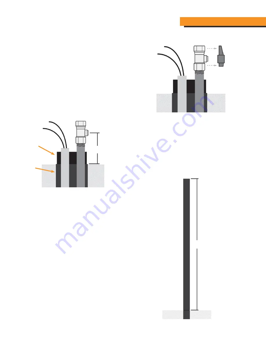
If you are installing the Manual Gas Shutoff on the Tiki Pole
(Option 2 from page 7) first remove the handle from the Ball
Valve and then install the ball valve on the ½” gas riser as shown
in diagram 3.
The use of pipe dope or Gas Teflon tape is highly recommended
to prevent a possible gas leak.
STEP 4
Once the Manual Gas Shutoff is installed measure from the
center of the Gas Shutoff to the top of the Black Base Pole.
This dimension we shall refer to as measurement “A”.
See diagram 4
STEP 5
Temporarily install the longer pole and measure from the
seam between the Base Pole and the top of the long tiki
pole. This dimension we will refer to as measurement “B”.
DIAGRAM 3
DIAGRAM 4
DIAGRAM 5
A
Base Pole
Inner Sleeve
B
TOP TORCH


