32
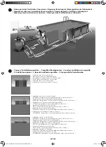
Connection of the filter system
CAUTION!
• Only a qualified electrician may connect the filter pump to the power supply.
• The power supply to the switch box must be disconnected via the quiescent current switch (FI switch) every time before working on the unit.
11a - Mount the pool filter as stated in the operating instructions.
11b - Connect the pool filter to the water circuit with the filter and heat pump.
The operating instructions of the filter pump must be observed strictly.
11
Connection of the heat pump (always connected to the filter system)
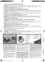
12a - Mount the supplied PVC pipes and fittings as shown on the drawing.
Note: Before adhering, first mount without adhesive to check that all parts fit correctly.
• Clean the pipe and the adapters using the paint stripper.
• Do not use sand paper to clean the smooth PVC pipe.
• The surface should be matt after cleaning. As soon as the surface has been cleaned, do not touch it again.
• Apply the adhesive in the longitudinal direction of the pipe and adapters.
• After applying the adhesive, join the two parts. Push the parts deeply into one another without turning them, and hold them briefly together in this position.
• Then use a brush to remove any excess adhesive.
12b - Set the bypass for operation
• For operation with a heat pump: Open valves 1 and 3, close valve 2.
• For operation without a heat pump: Open valve 2, close valves 1 and 3.
The operating instructions of the heat pump must be observed strictly.
12
Connection of the automatic ground suction unit - OPTIONAL, suction unit not included
8a - Insert the pressure regulator into the rubber adaptor. Make sure that you put it in the right way.
8b - Assemble the automatic pool cleaner pipe and fit it into the free end of the pressure regulator. It is important to expel all the air from it.
8c - Plug the whole unit, keeping it immersed, into the automatic pool cleaner point. Open the stop valve on the automatic pool cleaner point and shut off the
skimmer stop valve.
Start up the pump. When the pool cleaner is not in use, shut off the automatic pool cleaner point stop valve and open the skimmer stop valve. Refer to the notes
about the automatic pool cleaner for more details.
13
Electrical control box
CAUTION!
• Only a qualified electrician may install the switch box and connect the filter pump, counter flow pump, heat pump, counter flow
control unit and pool lighting.
• The power supply to the switch box must be disconnected via the quiescent current switch (FI switch) every time before working on the unit/case.
• This switch box may not be used as a junction box for non-related connection lines.
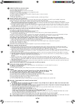
14a - Ensure that a qualified electrician connects the filter pump, counter flow pump, heat pump, counter flow control unit and pool lighting to the control box.
14b - Use the analogue timer for the filter pump and pool lighting to set the current time by turning the minute hand in the direction of the arrow.
14c - The selector switch on the two timers can be used to switch the filter pump and pool lighting on and off manually or control it via the time mode.
The times for which you want to control the time are shown near the ring. Push the teeth at which the power supply should be switched off inwards; the
remaining outer teeth represent the time during which the power supply should stay active.
14
I
On
Timer
O
Off
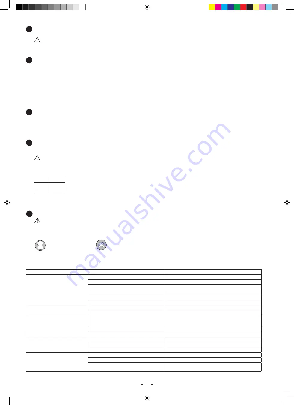
Troubleshooting instructions
Symptom
Possible cause
Recommended action
Pump is very loud and does not per-
form at a normal level
Motor runs in wrong direction
Rewire motor by switching the phases
Insufficient water level
Fill with water
Pump takes in air
Check connections for leaks
Valve is not quite open
Open valve
Suction line leaks
Remedy suction line leak
Pump is blocked (leaves etc.).
Clean pump
Pump is loud and brings full perfor-
mance
Motor hood rubs
Attach correctly
Fan hood is loose
Attach correctly
Pump does not start or starts sluggishly
and slowly
One phase is missing
Change supply line
When switched on, the FI switch
reacts
Wrong fuses
Use 16A slow fuse
An electrician should check the system
Motor cut-out switches off
Wrong setting
Set correct power value + 10%
Pump overheated
Allow motor to cool down and switch in again
Phase failed
Check fuse
Pump cannot be switched from the
pool
Switch hose bent or caught
Check whether the pump can be switched from the switch box
Switch hose too long
Shorten switch hose
Fuses/power supply/ motor cut-out
Check fuses/power supply test motor cut-out.
Commissioning and operation of the counter flow system
CAUTION!
• The system can only be started up if the pool is full. Always avoid allow the pump to run dry.
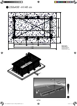
15a - Fill the pool with water up to max. half the height of the skimmer.
15b - Open both valves and switch on the system using the PN switch.
15c - Set the water current by turning the front inner nozzle. The maximum water current is achieved by turning the nozzle to the left.
To reduce the water nozzle, turn the nozzle to the right.
15d - Set the air injection by turning the front outer nozzles.
15e - Set the injection nozzle so that the swimmer float swims against the full jet.
15
Maximum flow
Minimum flow
NOTICE 250x450 - H140-2017 Urban Pool FINAL.indd 33
10.02.17 11:58

