background image

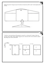
08

07

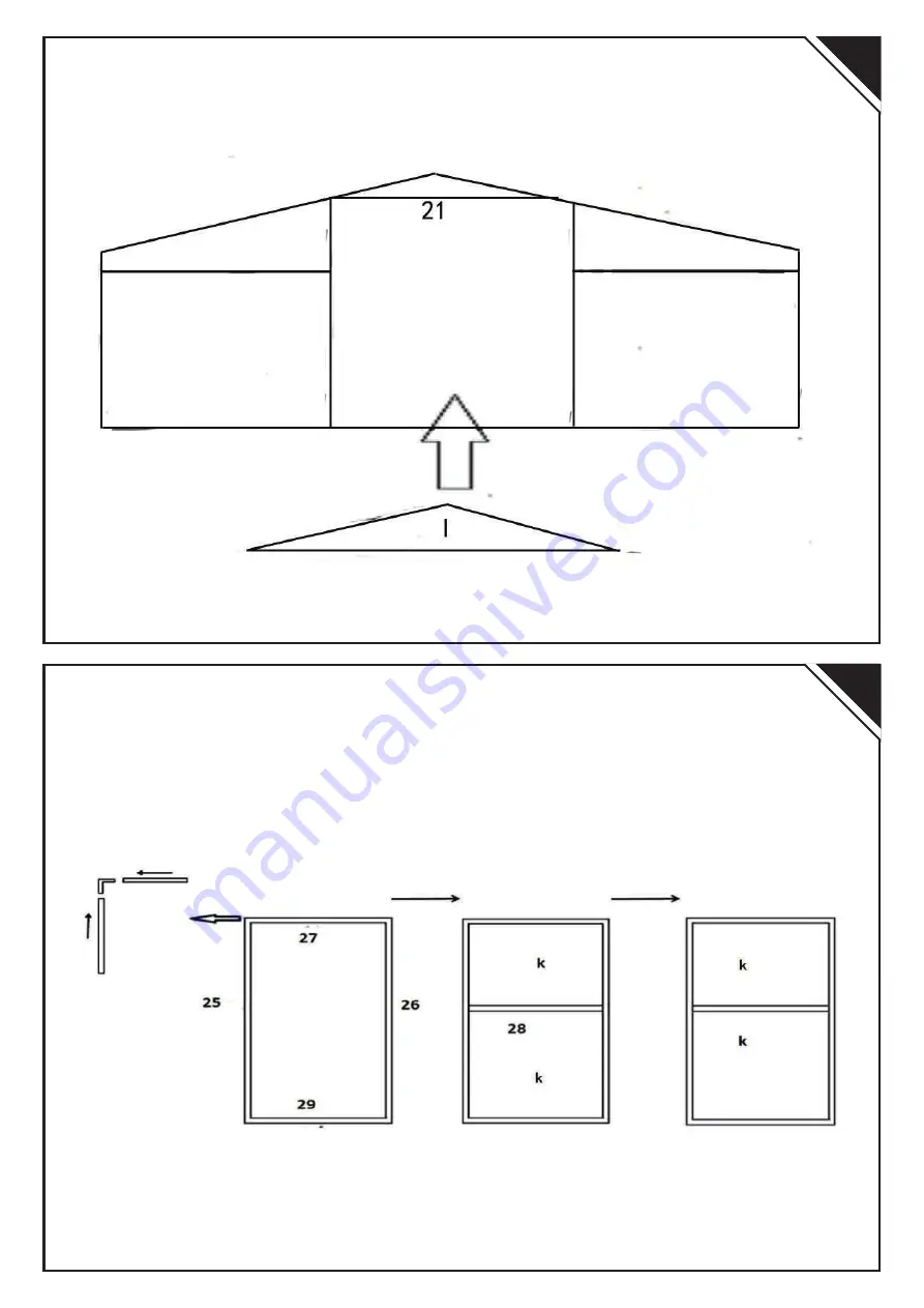
Slide PC panel I into grooves of 8,9 ,then connect 21 with 12 and 13,then tighten the 
screws

The door: Connect 25 and 27 by plastic connector ; slide one PC panel K into the 
groove of 27and 28; slide 28 with its groove to connect with K; then slide the other K 
into the groove of 26, 28 and 29

Summary of Contents for 845-243

Page 1: ...ASSEMBLY INSTRUCTION MANUAL READ AND SAVE THIS INSTRUCTIONS FOR FUTURE USE INbfc010V01 US _ 845 243 Tools Recommended...

Page 2: ......

Page 3: ...Y NO 1 2 3 4 5 6 7 8 9 10 11 12 13 14 15 16 17 18 19 20 21 22 23 24 25 26 27 28 29 30 31 32 33 1 33 2 34 36 37 38 39 40 41 42 43 44 45 46 A B C D E F G H I J K 1 1 1 1 4 1 1 2 1 1 1 1 1 1 1 1 4 2 2 2...

Page 4: ...PART L I S T...

Page 5: ...PART L I S T...

Page 6: ...PART L I S T...

Page 7: ...02 01 put 2 parts 5 connect with the base part 3 by plastic connector 32 In order to enhance the fastness of greenhouse adjust the screws put 12 and 13 connect with 3 by screw...

Page 8: ...04 03 slide PC panel G into groove 5 and 12 13 connect 19 with 5 by screw 39...

Page 9: ...06 05 Slide sunlight panels H into the grooves of 5 and 12 13 then tighten the screws Connect 8 with 9 by plastic connector 34 then connect 8 9 with 5 by connector 33 1 33 2...

Page 10: ...n connect 21 with 12 and 13 then tighten the screws The door Connect 25 and 27 by plastic connector slide one PC panel K into the groove of 27and 28 slide 28 with its groove to connect with K then sli...

Page 11: ...10 09 According to the above step assemble other side of greenhouse stand greenhouse connect 1 2 with front and back by connector 32...

Page 12: ...12 11 connect 6 7 with both ends of 5 by plastic connector 33 1 33 2 Connect both ends of 23 with 8 9 10 11 by plastic connector 34 slide the window into the groove of 23...

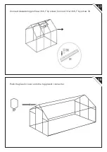
Page 13: ...14 13 Connect 23 with plastic connector 34 by screw 42 Connect 16 17 18 with 6 7 23 by screws but keep the screws loose for later PC panels assembly then connect 18 with 24...

Page 14: ...16 15 Slide PC panels A the wall B the roof and J the roof into the grooves of 17and 18 then tighten the screws...

Page 15: ...18 17 Connect dewatering pro le with 6 7 by screw Connect 31 with 6 7 by screw 38 Push the plastic cover onto the top plastic connector...

Page 16: ...D o n e Put 44 on inside 4 base corner then connect screw 46 and 45 xed in to the oor...

Page 17: ......

Reviews: