Architectural Products by Outwater assumes no liability for improper installation.
Page 8
BOTTOM LADDER HARDWARE
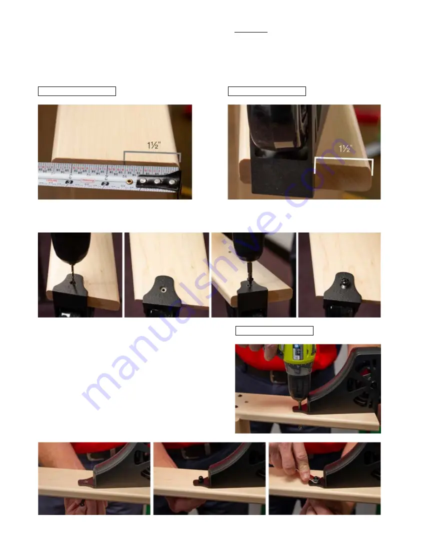
1. Mark a line on the bottom of each side rail 1 1/2” in from the front edge
(figure 16)
.
2. Line up the Bottom Wheel Housing to the line drawn on the bottom of the side rail of the ladder using the
“U” bracket portion of the housing. Verify that the bracket is flush with the bottom of the ladder. Because
of the 12-degree angle of the bottom of the ladder this will align the housing diagonally across the ladder
side rail
(figure 17)
.
FIGURE 16
FIGURE 17
FIGURE 18
3. Using a 1/8” drill bit, pre-drill the hole for the Phillips-drive pan-head 3/4” long screw and secure the Bottom
Wheel Housing to the inside of the ladder side rail
(see below)
.
4. Using a 1/4” drill bit and the top fastener hole in the
Bottom Wheel Housing as a guide, drill a through
hole in the ladder side rail
(figure 18)
.
5. Use the nut cap/threaded rod and the acorn nut to
fasten the top of the Bottom Wheel Housing to the
ladder side rail (using a 4mm Allen wrench and a
10mm open end wrench).
(see the three images below)
.
Summary of Contents for architectural products E-GLIDE EG.300 Series
Page 12: ...REV 08 13 20 ...


