B-526-10N-E
16
6. INSTALLATION
6.1 Flowmeter
(1)
①
Sizes 82 through 84
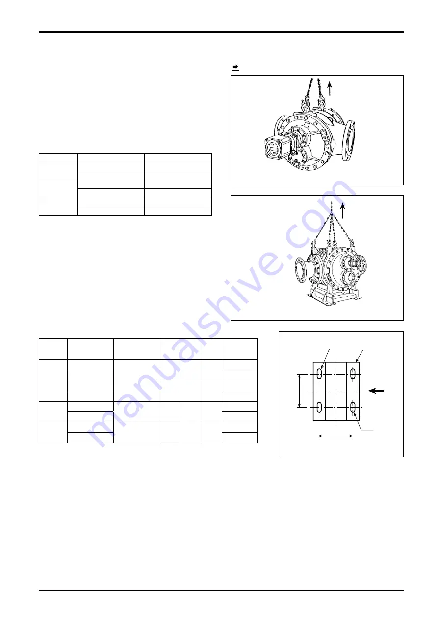
Transport the meter to the installation location by
hanging with a wheel crane (capacity one ton or
greater), or similar equipment as shown in Fig.
6.1, exercising care not to give impact shock and
install it in place.
Table 6.1 Approximate Weights of Flowmeter
Meter Size Nominal Size
Approx. Weight, kg
82
100 (4
″
)
200
150 (6
″
)*
210
83
150 (6
″
)
300
200 (8
″
)*
310
84
200 (8
″
)
425
250 (10
″
)*
435
*: Standard.
All dimensions in millimeters
②
Sizes 85 through 88
1. Transport the meter to the installation location
by hanging with a wheel crane (capacity one
ton or greater), or similar equipment as shown
in Fig. 6.2, exercising care not to give impact
shock and install it in place.
2. A strong concrete foundation is required for
the installation location. Install anchor bolts
according to the dimensions given in Fig. 6.3.
Table 6.2 Foundation Bolt Dimensions and Approx. Meter Weight
Meter
Size
Nom. Dia. mm Anchor Bolt
A
B
h
Approx.
Wt.
85
250 (10
″
)
M24-600
640
550
φ
30
×
50
1200
☆
300 (12
″
)*
1250
86
300 (12
″
)
M30-700
700
650
φ
36
×
56
1500
☆
350 (14
″
)*
1530
87
350 (14
″
)
M30-700
780
700
φ
36
×
56
2200
☆
400 (16
″
)*
2500
88
400 (16
″
)
M36-750
950
950
φ
42
×
62
3800
☆
450 (18
″
)*
4600
*: Standard.
All dimensions in millimeters
NOTE: For outline dimensions and piping dimensions, see the approval
drawing.
See the TYPICAL INSTALLATION on page 18.
HOIST
Fig. 6.1
HOIST
FLOWMETER
Fig. 6.2
FLOW
DIRECTION
A
B
FOUNDATION BOLT
BASE
h
Fig. 6.3
(2) Install the meter on the discharge side of the pump.
(3) Take care not to cause piping stress.
(4) Allow a working space for disassembly and inspection. A space at least one meter around the meter is
necessary.
Summary of Contents for ULTRA UF-II
Page 67: ...B 526 10N E 67...


