B-526-10N-E
Smart Type
24
9. OPERATING INSTRUCTIONS
9.1 Operations Sequence
(1) Read well the information stated on the nameplate before commencing operation and make sure the
operating conditions conform to the specification.
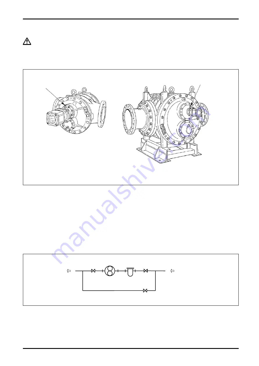
(2) At first time operation with actual fluid, let air in each bearing out through vent plugs (see Fig. 9.1 below).
AIR VENT VALVE (4 PLC'S)
AIR VENT VALVE
(4 PLC'S)
(Sizes 82 through 84)
(Sizes 85 through 88)
Fig. 9.1
(3) Carefully follow the valve operations sequence given below (refer to the piping diagram below):
①
Shut off the valves (A) and (B).
②
Progressively open the valve (C) to allow the fluid in the bypass line.
③
Slightly open the valves (A) and (B). If necessary, slightly close the valve (C). The flowrate at this point is
correct if the register pointer moves slightly.
④
In applications where temperature exceeds 80
°
C, run the meter at least for 10 minutes in the conditions
(3) to ensure uniform heat distribution in the measuring chamber.
⑤
Following the preheating period above, progressively close the valve (C) in the bypass line and
progressively open the valves (A) and (B) until the rated flow is reached.
⑥
) Flowrate should be regulated with the valve (B) downstream of the meter and should be held within the
rating.
BYPASS LINE
METER
STRAINER
VALVE
FLOW DIRECTION
A
B
C
(4) The strainer net should be inspected for condition and cleaned on a regular basis. On a new installation, in
particular, inspect daily first and, according to the clogged condition of the net being observed, inspection
intervals may be reduced progressively to, say, once in two or three days.
Summary of Contents for ULTRA UF-II
Page 67: ...B 526 10N E 67...


