B-526-10N-E
34
10.2.2 Assembly
The assembly procedure is essentially reverse of the removal procedure except for some difference in the
order.
(1) Apply turbine oil to the bearing bore and install two rear bearing holders (208). Then install blind cover (105)
in alignment with match marks. Do not forget to install O-rings (211 and 112).
NOTE:
①
Individual bearing holders are identified by metal stamped numbers: install the one in place with the
same number metal stamped on the rear cover.
②
Install the non-turn pin of bearing holder in
line with the non-turn opening in the rare
cover (103).
③
Do not fail to install the O-ring (211) for
bearing holder. Failure to install it in place will
cause rotor seizure. Thoroughly clean
individual component parts. Keep grit and
grime out at reassembly.
(2) Place the meter body upside down with the rear
cover down (place horizontally on supporting
blocks).
(3) Apply turbine oil on rotor shafts and install the
rotors.
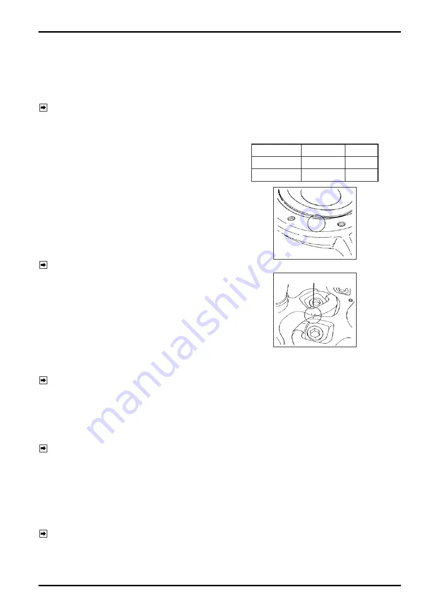
NOTE:
①
Be sure to align match marks at rotor
installation as shown.
②
Exercise care to avoid bumping the edges of
bearing shaft (203) while fitting the shaft into
the bearing.
Using a chain block, carefully lower the rotor
being guided by the measuring chamber.
(4) Install the front cover (102). Place it on the meter
body in line with match marks. (Ensure that an
O-ring is in place.)
NOTE:
①
Care should be taken to avoid bumping against the shaft and thrust ring
②
Drive in locating pin (107) firmly.
(5) Tighten hex bolts and then install thrust ring.
(6) Apply turbine oil to the bearing bore and, making sure of the identification number of bearing holder (208),
install in place.
NOTE:
①
Ensure that bearing holders are in place with their identification numbers matched.
②
Do not forget to install an O-ring (211) in place.
(7) Install the adapter (104) and bearing blind cover (105) in line with their match marks.
(8) Place the meter body sideways on the base.
(9) Confirm the rotation of rotors
Using a wooden rod or similar object, apply it to the gear teeth through the meter inlet/outlet opening and
move the rotors to make sure of their rotation, perhaps heavy to move them, though.
NOTE:
See pages 30 and 31 for the procedure to recondition rotor gear teeth and the precautions at signal magnet
disassembly and reassembly, Sizes 82 and 83.
Table 10.3 Bearing Numbers
Register side Rear side
1st rotor
1
3
2nd rotor
2
4
1
MATCH MARKS
Summary of Contents for ULTRA UF-II
Page 67: ...B 526 10N E 67...


