B-526-10N-E
43
11.5.3 About Dummy Output Features (special functions)
By the following steps, a 1 Hz or 10Hz
simulated factored pulse
train can be furnished irrespective of
flowmeter measurement.
NOTE: This feature is not available with the unfactored pulse output specification.
◦
1Hz simulated output mode (dummy output 1 mode Code: Pd1)
①
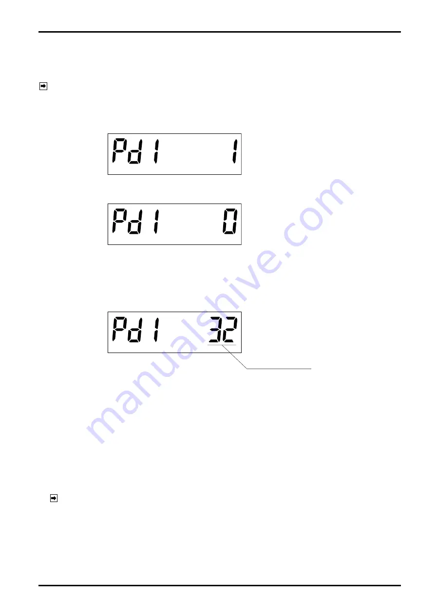
According to the Table 8.4 "Menu Trees and Switch Operation" (page 22), show dummy output 1 ("Pd1 1")
on the LCD.
(2) Turn MODE button ON for 2 seconds to go to the dummy output run mode.
(The display shows "Pd1 0.")
(3) Operation within the dummy output run mode
◦
Turn RESET button ON
→
4 Dummy output appears and the counter counts in sync with the pulse
output produced.
◦
Turn MODE button ON
→
Dummy output stops.
◦
Hold MODE button turned ON for 2 seconds
→
Dummy output run mode is terminated, returning to the
state
①
.
Number of output pulses
※
The procedure above also applies to the 10Hz simulated output mode (dummy output 2 mode Code:
Pd2).
※
Pulse width is set by parameter Pon.
11.5.4 Parameter Initialization
(1) Remove the external power source.
(2) Holding the selector magnet close to the MODE switch, turn the battery switch (SW2-6) from OFF to ON.
(3) The LCD lights up in all figure places. (The selector magnet is held in proximity.)
(4) When the screen shows "PA. rESEt," remove the selector magnet to turn "OFF"
→
Initialization is complete.
(Holding the magnet in proximity while "PA. rESEt" is shown causes the modes to go to the measure
mode without initialization.)
NOTE: Parameter initialization is the step to be taken upon detection of a parameter error "PA.Err 1" or
other erratic condition. Do not take this step unless absolutely necessary.
Summary of Contents for ULTRA UF-II
Page 67: ...B 526 10N E 67...


