12
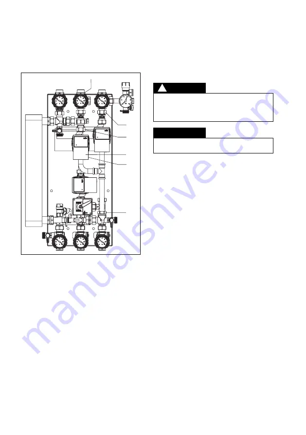
3. Install existing pump (illustr. 5.3)
3.1. Install existing pump (5) as illustrated. To do
so, fit the pump and the EPDM seals and hand
tighten the collar nuts (6).
3.2. Align all components and tighten all collar nuts
(3 and 6).
Illustr. 5.3 Install existing pump
4. Installation of the “Regtronic S-Bus” interface
adapter
4.1. Open the casing cover of the controller
“Regtronic RX-B” and connect the V-Bus con-
nection of the “Regtronic S-Bus” interface
adapter to the controller (see illustr. 5.4). The
polarity is optional. The connection cables are
enclosed with the interface adapter.
Please make sure that the electronic components
are disconnected from the power supply when
opening the casing cover as a voltage of 230 V is
supplied.
DANGER
!
4.2. Connect the PWM wire of the “Wilo Yonos
Para” to the PWM / 0-10V output of the inter-
face adapter (brown = 5, blue = 6).)
4.3. Carry out electrical connection from the
controller (R3/N/PE) to the pump.
4.4. Select the relay via which the speed informa-
tion shall be converted into a corresponding
PWM signal via the DIP switches for relay ad-
dressing. Factory setting of the “Regtronic
RX-B” controller is relay 3 (see illustr. 5.5).
(Details regarding relay addressing: See
enclosed installation instructions interface
adapter “Regtronic S-Bus”, chapter 5).
4.5. Jumper setting “A+B = PWM” (see illustr. 5.5).
4.6. Installation of the switching module outside
the station (wall installation).
The correct allocation of the controller sensors to
the solar pumps must be observed (R1, R3)!
NOTICE
4
3
6
6
5
3


