11
115V
1 PH
208
230V
3 PH
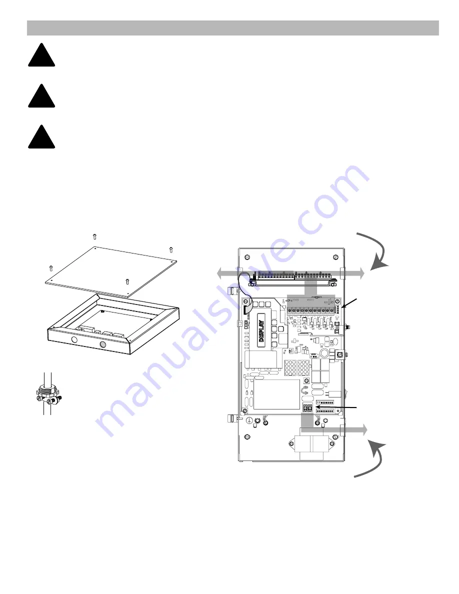
Route Low Voltage Wiring
in Shaded Areas as Shown
Radio Control
Plug
Blu=24VDC
Org=Relay
Yel =Gnd
L1 -I- N
Route Line Voltage Wiring
in Shaded Areas as Shown
Fig.4C
Wiring to TCM
Remove knockout
CONNECT INTERFACE TO OPERATOR
IMPORTANT NOTE:
Cables included with this kit are 4 feet long. If junction box is more than 3 feet
away from operator, additional wires and connections will be required to lengthen wires.
This junction box must be mounted indoors.
!
1. Install cord grip or conduit connector to interface junction box for control harnesses.
2. Plug 6 and 10 conductor harnesses into J2 & J1 connectors on interface board.
3. Route wire into operator using cord grips or conduit.
4. ONLY use low voltage inputs to operator. DO NOT route wire into operator through high voltage inputs.
5. Install wiring in operator per charts and wire diagrams on following pages.
IMPORTANT NOTE:
Operator must have the Auxiliary Output Module (AOM) (P/N OPABIOGX.S)
installed. Contact your local distributor for module installation.
!
IMPORTANT NOTE:
If using remote controls to operate opener, an external radio must be used to
activate this countdown timer.
!
Install 1/2in. NPT or other suitable
connector into enclosure. (Adhere
to local electrical code(s) and
regulations).


