background image

11

1.  Plug door lock harness into the LOCK plug on bottom of opener. Insert plug in correct direction 

(SEE INSET)

2.  Run wire down the wall to the DOOR LOCK and secure with supplied wire staples. NOTE that DOOR LOCK 

wires are polarity sensitive.

3.  Cut off excess wire, strip 1/4” of insulation and attach to bottom connectors on DOOR LOCK.

4.  Install WHITE wire to W terminal and STRIPED wire to B/W terminal.

Wire Door Lock

WIRE THE OPENER

ALL WIRE CONNECTIONS LOCATED AT BOTTOM OF OPENER

4

Door Lock Plug

Door Lock Wire Connections

Summary of Contents for INFINITY 2000

Page 1: ...ge to property use this opener only with a residential sectional door with front torsion springs WARNING DO NOT use photocells from other manufacturers or openers with this opener 40686503927 07 2019 2019 Overhead Door Corporation Overhead Door the Ribbon logo Infinity CodeDodger OHD Anywhere and Safe T Beam are registered trademarks of Overhead Door Corporation Overhead Door Corporation All other...

Page 2: ...t Safety Instructions 32 Regular Maintenance Schedule 33 Door Inspection Maintenance 33 Remote Battery Replacement 33 Troubleshooting LED Signals 34 36 Replacement Parts 37 39 DASMA Information 40 41 INDEX SAVE THESE INSTRUCTIONS READ AND FOLLOW ALL INSTRUCTIONS FCC Part 15 21 Statement Changes or modifications not expressly approved by the party responsible for compliance could void the user s au...

Page 3: ...uetooth LED Light Fixture Lighting Fixture turns ON when door is activated and automatically turns OFF 4 minutes later Can be activated deactivated manually from the wall console 5 Integrated OHD Anywhere Available with select models allows operation of the garage door opener with a secure mobile device application app from OHD Anywhere 6 Wireless Wall Console Wireless Wall Console operates door o...

Page 4: ...Sécurité DANGER POTENTIEL EFFET PRÉVENTION PORTE EN MOUVEMENT AVERTISSEMENT Pourrait entraîner des blessures graves voire la mort Utiliser uniquement si la porte est en vue et libre de tout obstacle Ne laisser personne se tenir dans l ouverture de la porte pendant qu elle est en mouvement Ne pas permettre aux enfants de jouer avec l opérateur de la porte Ne pas modifier la commande de l opérateur ...

Page 5: ...her adjacent walking surface so small children are not able to reach it and c away from all moving parts of the door Install the entrapment WARNING label next to the wall button or console in a prominent location Install the emergency release handle on the emergency release cord The opener must reverse when the door contacts a 1 1 2 inch high object on the floor at the center of the doorway This i...

Page 6: ...ide to side if there is CONTACT A TRAINED DOOR SYSTEM TECHNICIAN otherwise opener reliability will be significantly reduced FRONT VIEW WARNING Garage door hardware springs cables brackets pulleys etc are under extreme pressure and tension DO NOT attempt to repair or adjust door springs or any hardware and DO NOT OPERATE garage door automatically or manually if door is improperly balanced or spring...

Page 7: ...ect permanent power input cable to harness wires using approved connectors or wire nuts Adhere to local electrical code s and regulations 10 Install ground connector to permanent power cable ground wire 11 Install ground screw and power cable ground onto chassis 12 Plug power input harness into transformer harness 13 Install transformer 14 Ensure input power cable and connections do not interfere ...

Page 8: ...ame process for the left hand Red cable keeper assembly NOTE It is recommended that wood doors be pre drilled with 1 8 pilot holes prior to fastening IMPORTANT NOTE Operate door manually full open to full close and watch keeper to ensure that it does not contact door track Adjust as necessary Bottom Corner Bracket Spacer Shaft Track Roller 1 8 1 2 Min 4 1 2 Max FLOOR Cable Keeper Assembly Cable Ke...

Page 9: ... below 4 Tighten 3 inner set screws on coupler finger tight against opener output shaft NOTE The coupler must be installed onto the opener output shaft until the coupler seats completely to the recess inside coupler NOTE Opener MUST be mounted to garage framing material DO NOT install to particle board or drywall NOTE Alternate installation method If dimension D page 4 is less than 8 install coupl...

Page 10: ...screws onto door shaft finger tight NOTE The mounting of this opener to the door shaft is designed so the door shaft will slide through the coupler and enter the hollow output shaft of the opener up to 3 3 8 there is a stop pin located in the center of the opener output shaft INSTALLING THE OPENER CONT DOOR DOOR TORSION SHAFT CABLE DRUM RELEASE CABLE SOLID OR HOLLOW DOOR SHAFT NO KEY SOLID KEYED D...

Page 11: ...ow tube or 1 2 turn for solid shaft on each coupler set screw in 1 4 turn increments after contacting door and opener shaft surfaces DO NOT tighten set screws into an empty keyway Leave at least a 1 4 gap between coupler and door shaft bearing Tighten mounting bracket bolt to opener Pull emergency release cable and manually operate door to inspect for binding Tie RED emergency release cord to cabl...

Page 12: ...re punched door lock bar cutouts as shown below Remove template from the back page of the owners manual Apply template to the door track where the center 7 16 hole is approximately 3 inches above the door roller on the 2nd or 3rd door panel Drill two 9 32 holes for mounting and one 7 16 hole if using template De burr holes if required 2 Position door lock and install two 1 4 X 9 16 track bolts and...

Page 13: ...re with supplied wire staples NOTE that DOOR LOCK wires are polarity sensitive 3 Cut off excess wire strip 1 4 of insulation and attach to bottom connectors on DOOR LOCK 4 Install WHITE wire to W terminal and STRIPED wire to B W terminal Wire Door Lock WIRE THE OPENER ALL WIRE CONNECTIONS LOCATED AT BOTTOM OF OPENER 4 Door Lock Plug Door Lock Wire Connections ...

Page 14: ...e the wire to the walls using the insulated staples 4 On the powerhead Remove 1 4 insulation from both sets of white and striped wire Twist two white wires together Using a small flat head screwdriver press in the orange tab at one STB terminal and insert the wires Twist the two striped wires together and insert into the other STB terminal NOTE that STB wires are not polarity sensitive 5 At each s...

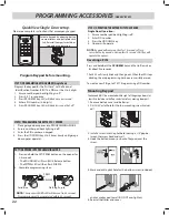
Page 15: ...place 6 Remove upper battery door and remove protective tab and batteries 7 Install top screw to secure console to the wall 8 Install batteries and battery door 9 Install warning decal in the same area as wireless wall console Open cover and remove battery tab before programming Lower mounting slot AAA AAA Mounting Screws Drywall Anchors 1 DOOR Button Runs garage door opener 2 DELAY Button Adds a ...

Page 16: ...rs will be required not provided B W W Wall Console Wires Striped Wire to B W Terminal White Wire to W Terminal FINISHING THE INSTALLATION Install Bottom Cover Onto Opener OMIT THIS STEP IF INSTALLING BATTERY BACK UP 1 Remove two screws on the sides of opener 2 Route wires to the rear of opener to align with slot in rear of cover 3 Install cover with screws removed in step 1 B W Main Activation Su...

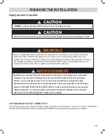
Page 17: ...ques mises à la terre NE PAS modifier la fiche dune quelconque manière Si vous n avez pas de prises mises à la terre faites en installer par un électricien agréé L opérateur doit être correctement mis à la terre pour éviter les blessures corporelles et des dommages matériels NE JAMAIS UTILISER DE RALLONGE Vérifiez les codes locaux des bâtiments pour connexions câblées permanente Les connexions câb...

Page 18: ...ges should be used if adding additional remote controls wireless wall consoles or light fixtures 8 Accessory Installation and or Programming 9 Program wireless keypad If applicable 10 Program built in vehicle remote If applicable 11 Program the Integrated OHD Anywhere If applicable 12 Install Battery Backup BBU If applicable NOTE Eachprogrammingstephasa30secondtimelimitforcompletionafterthefunctio...

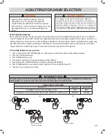
Page 19: ...f 7 Opener is now ready to set limits DRUM SELECTION CHART DRUM TYPE Long LED Round LED Standard 4 inch or less diameter drum RED RED Standard or High Lift greater than 4 inch diameter or Vertical Lift PURPLE PURPLE BLUE Press to adjust See Chart for selection Lock selection X2 1 2 3 4 5 Operator drum selection settings must be adjusted for use on Standard or High Lift residential doors with drum ...

Page 20: ...RT WITH DOOR FULLY OPEN OR CLOSED 1 Press and hold the DOWN arrow button on the opener for 2 5 seconds The LONG LED will turn BLUE Release button The LONG LED will then flash BLUE 2 Press and hold the DOWN arrow button until door is fully closed Use both UP and DOWN buttons to adjust close travel as necessary Door should rest on the floor until the weather strip is compressed enough to seal along ...

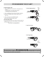
Page 21: ...imit is now programmed Programming UP Limit SECTIONAL DOOR UP LIMIT Door should fully open so that door seal is about even with door header Do not adjust so much that the door will bend buckle or stretch door spring cables backward Steady Blue HOLD UNTIL LED Lights Flashing Blue RELEASE 1 2 Enter Programming Mode 3 Adjust Door Position 4 Lock Programming Flashing Blue PRESS RELEASE PROGRAMMING THE...

Page 22: ...to complete this setting 1 With the garage door open lay a 2 X 4 board flat on the floor at the center of the door opening 2 Close the garage door using the wall control When the door contacts the board it should stop and reverse direction within 2 seconds to the full open position The long LED light on the powerhead will begin to flash RED with the reversal of the door Remove the 2 x 4 board and ...

Page 23: ...slowly press and release the desired button on the remote two times Both opener LEDs will flash and turn off indicating the remote has been programmed 4 Press the desired remote button again The opener should run To program the same remote for other garage door openers repeat the steps above using one of the other remaining remote buttons REPEAT STEPS 1 TO 4 FOR EACH OPENER AND REMOTE NOTE It is p...

Page 24: ...w Single Door setup Please see complete instructions that accompany keypad Resetting a PIN Press and hold both the PROGRAM key and the Up Down key for about five seconds The LED s will slowly blink and then go out When the LED stops blinking the old programming has been successfully erased To create a new PIN go to STEP 1 Programming a PIN number Mounting Keypad The keypad MUST be mounted within s...

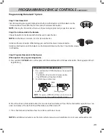
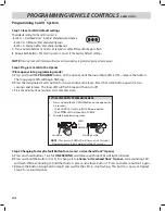
Page 25: ...er Place opener into programming mode A Press and hold the PRGM button on the opener until the round blue LED is ON Release the button The long purple LED will begin flashing PROGRAMMING VEHICLE CONTROLS ABBREVIATED B Press the chosen HomeLink button for two seconds and release Press that same button again for two sec onds and release The both LEDs will flash blue and then turn off C Press the Hom...

Page 26: ...nd release The long LED will flash blue and then turn off C Press the Car2U button a few times more until door moves Step 3 Changing Factory Default Button for a Genie or Overhead Door Opener A Press and hold buttons 1 3 for ONE SECOND and release all three LEDs will light solid red B Press and hold the button 2 or 3 to change it to a Genie or Overhead Door Opener corresponding LED will flash Whil...

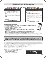
Page 27: ... operated from the app wall console or remote control Show reports for opener usage showing dates and times when the opener was operated Show reports of who operated the opener when used from another user on the account Set custom RULES for predetermined times to automatically close a chosen door and or notify of its operation Opener light system and an audible signal will activate as a warning th...

Page 28: ... to garage door openers wall button NOTE This placard should be used in lieu of the standard WARNING placard included with this opener Install WARNING placard 4 Versions 8 and higher Versions 4 4 and higher INSTALLER LEAVE THIS MANUAL WITH HOMEOWNER HOMEOWNER SAVE THIS MANUAL FOR FUTURE REFERENCE RESIDENTIAL WALL MOUNT OPENER INSTALLATION PROGRAMMING OPERATION MAINTENANCE MANUAL 12345678910 10 201...

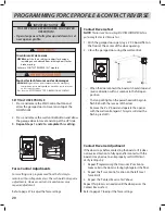
Page 29: ...ce setting is shown SEE CHART 3 Press release the PRGM button to lock the desired UP FORCE setting Both LEDs will turn BLUE then go out confirming that the UP force setting has been changed and is locked LEDs will now show the current DOWN FORCE setting SEE CHART 4 Press either the UP or DOWN arrow button until desired DOWN force setting is shown SEE CHART 5 Press release the PRGM button to lock t...

Page 30: ...th LEDs will turn off indicating that all remotes have been erased 3 Press any remote button The opener should NOT run 1 Enter Programming Mode Solid Blue Flashing Purple 2 Press and Hold UP DOWN Buttons 2 5 seconds 3 Test Remote Release when LEDs turn BLUE SPECIAL INSTALLATION INFORMATION 3 Test Wireless Wall Console 1 Enter Programming Mode Solid Blue Flashing Purple 2 Press and Hold UP DOWN But...

Page 31: ...use Safe T Beams that are included with this opener DO NOT use other brands or types of photocells on this opener Source RED LED Sensor Green LED Possible Problem Solution ON ON Normal Operation None Required OFF OFF Opener not powered Wiring from opener bad Check breakers fuses plugs Check wiring for shorts OFF ON Wiring to source missing or bad Power has been interrupted Check wiring Remove powe...

Page 32: ...658 0002 S POURÉVITERLESBLESSURES GRAVESVOIREMORTELLEPAR ÉLECTROCUATIONPOURRÉDUIREESLESRISQUES D INCENDIE Débranchertouteslessourcesd alimentationélectriqueset lapileavantd effectuerdesopérationsderéparationou d entretien ATTENTION Testing The Battery Backup NOTE It is recommended that the battery backup be allowed to charge for 24 to 48 hours prior to testing Initially the opener may not operate ...

Page 33: ...ctric shock This plug will fit in a polarized outlet only one way If the plug does not fit fully in the outlet reverse the plug If it still does not fit contact a qualified electrician Never use with an extension cord unless plug can be fully inserted Do not alter the plug INSTALLING ADDITIONAL LIGHT KITS UP TO 3 LIGHT KITS TOTAL 1 Press and hold the SET PRGM button on the opener for 2 5 seconds T...

Page 34: ...evere injury or death Have a trained door system technician make repairs to cables spring assemblies and other hardware 8 This operator system is equipped with an unattended operation feature The door could move unexpectedly NO ONE SHOULD CROSS THE PATH OF THE MOVING DOOR SAVE THESE INSTRUCTIONS Pour réduire le risque de blessures graves voire mortelles lire et comprendre toutes les instructions 1...

Page 35: ...ergency release cord down and release quickly to engage opener to door Operate door using remote or wall control A WARNING Garage door hardware springs cables brackets pulleys etc are under extreme pressure and tension DO NOT attempt to repair or adjust door springs or any hardware and DO NOT OPERATE garage door automatically or manually if door is improperly balanced or springs are broken CONTACT...

Page 36: ...c Door starts down then STOPS and goes back up OR Safe T Beam System malfunction If NEW Installation make sure ONLY the Safe T Beams that came with this opener are installed Check if limits are properly set see pages 18 19 Adjust limits as needed Check if Safe T Beam red LED is flashing See page 29 Safe T Beam system check Check Safe T Beam system for beam obstruction or misalignment of lenses See...

Page 37: ... local door service professional NEVER try to repair door hardware or springs yourself Check opener Door Lock and wire connections see page 11 Door will only run closed If applicable turn Sure Lock OFF with Basic Wall Console see page 14 Check if limits are properly set see pages 18 19 Check door balance condition and door spring see page 33 Check opening FORCE control see page 20 and Force settin...

Page 38: ...ure detected Check door spring track rollers hinges and fixtures OFF ON RED STEADY Thermal cutout DO NOT unplug unit Wait until LED clears before operating PULSING RED FLASH Interlock Open Check missing wire from interlock terminal Inspect interlock see page 14 ON PURPLE STEADY ON PURPLE STEADY Component error Contact a trained door system technician OFF ON BLUE FLASHING Door will not open Check S...

Page 39: ...reless Wall Console 39774R S Light Fixture 39945R S Low Voltage Power Input Kit 40984R S TorqueMaster Adapter Kit 41032R S Alternate Mounting Kit 40803R S Specify model number of opener when ordering parts Hardware Bag Staples Lag Bolt Mounting Bracket Emergency Release Cord Emergency Release Handle Cable Keeper Kit Door Lock Coupler Wireless Wall Console BlueTooth LED LIGHT FIXTURE PARTS SERVICE ...

Page 40: ... Integrated OHD Anywhere Control Board Kit 1 4 Transformer Kit 1 5 Chain assembly 16 Loop 1 2 P 1 6 Shaft Assembly Kit 1 7 Motor Assembly Kit 1 8 MLS Travel Limit Kit 1 9 Release Assembly Kit 1 10 Side Panel Assembly RH 1 11 Side Panel Assembly LH 1 12 Bottom Cover 1 13 Center Brace 1 14 Battery Backup Battery 1 15 Battery Backup housing 1 ...

Page 41: ...39 1 2 3 4 5 6 7 8 9 10 11 12 13 14 15 18 ...

Page 42: ...hit by a closing garage door or from being trapped under the door A few simple precautions can protect our family and friends from potential harm Please take a few minutes to read the following safety and maintenance tips Refer to your garage door and opener owner s manual for details specific to your garage door and automatic opener Do not stand or walk under a moving door Do not let children or ...

Page 43: ... to play with or use garage door opener controls can lead to tragic results Discuss garage door safety with your children Explain the danger of being trapped under the door Teach children to keep their hands and fingers clear of section joints hinges track springs and other door parts Contact with a moving door or its hardware could cause injury These injuries can also happen with garage doors tha...

Page 44: ...DOOR LOCK TEMPLATE 7 16 9 32 9 32 OVERHEAD DOOR CORPORATION OPERATOR DIVISION 1 Door Drive Mount Hope OH 44666 1 800 929 3667 www overheaddoor com ...

Reviews: