28
Chapter 2 - Installation
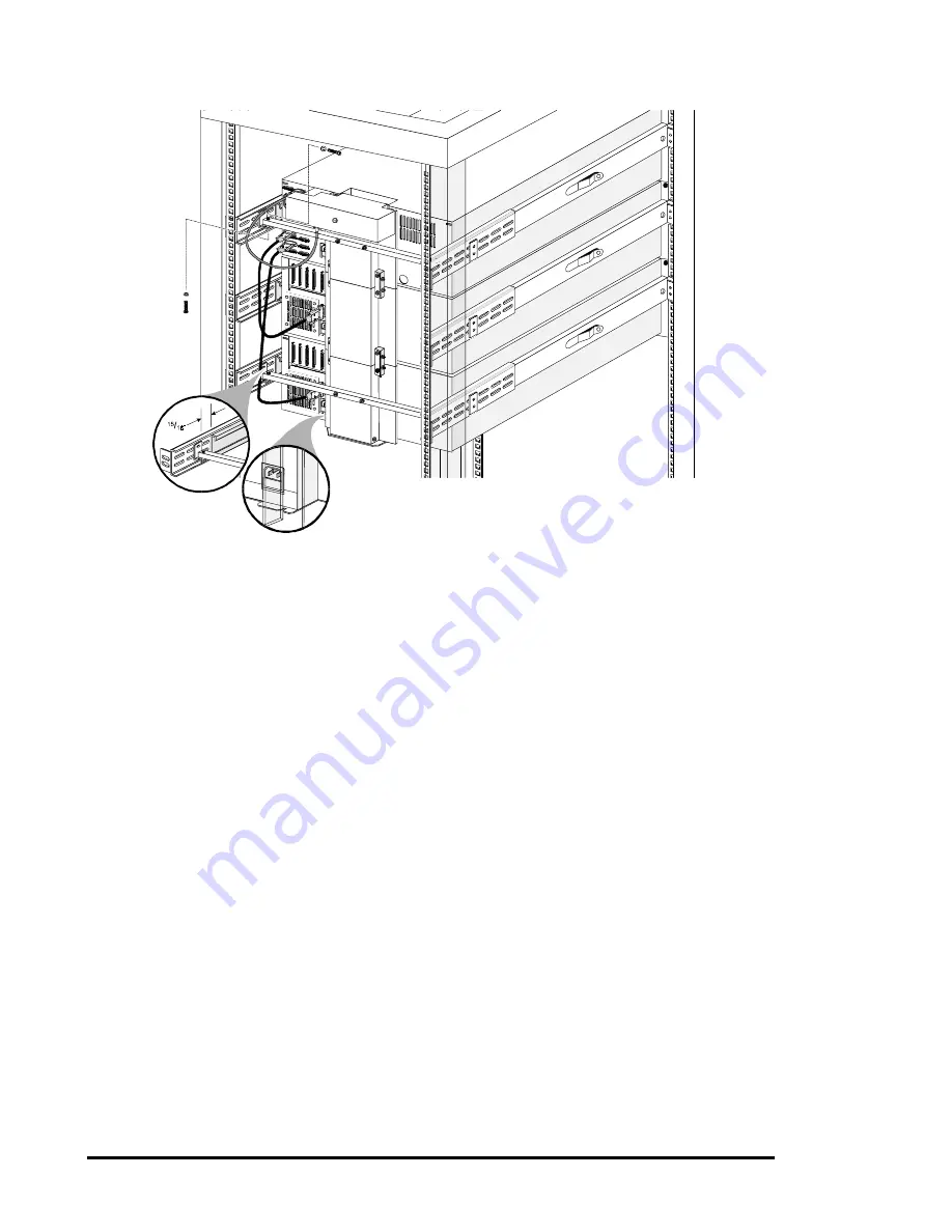
Figure 2-12
Installing the XpressChannel in the Rack
4.
Ensure that the bottom edge of the XpressChannel base section is flush with the
bottom surface of the module chassis. If necessary, adjust the vertical position of the
angle brackets.
5.
Repeat steps 3 and 4 at the bottom module. Tighten all of the screws that hold the
XpressChannel to the angle brackets while ensuring that:
a)
The XpressChannel is centered horizontally, as indicated by the flange
engaging the slot on the top and bottom modules, and
b)
It is centered vertically, as indicated by the bottom of the bottom of the
XpressChannel being flush with the bottom of the lowest module, and
c)
The XpressChannel is pressed firmly against the backs of the top and bottom
modules.
6. One by one, push the remaining modules into place and tighten the captive screws. In
each case, ensure that the module does not bind against an adjacent module, that
clearance between modules is evenly divided between top and bottom, and that the
flange on the XpressChannel engages the slot on the back of the module.
7. If binding occurs, or if the module is not centered on the XpressChannel, loosen the
four screws that secure the slides of the binding module to the front rails and the four
screws that secure the slides to the rear rails, reposition the slides, then retighten the
screws.
8. If necessary, repeat steps 6 and 7 until the module does not bind against the slides or
against adjacent modules.
9. Repeat steps 6, 7, and 8 for all of the remaining modules.
Summary of Contents for DLT LibraryXpress Series
Page 8: ......
Page 20: ......
Page 52: ......
Page 80: ......
Page 92: ......
Page 130: ......
Page 134: ...126 Appendix A Specifications...
Page 135: ...Appendix A Specifications 127 a p a c i t y C C a pa city C C...
Page 136: ...128 Appendix A Specifications...
Page 138: ......
Page 140: ......


