background image

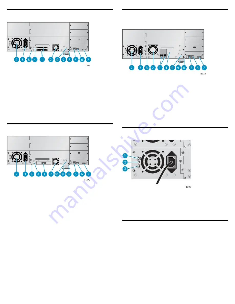
Back panel overview: parallel SCSI

2. Fan

1. 68-pin HD parallel SCSI
connectors

4. Tape drive assembly

3. Power connector

6. Serial port (Factory use only)

5. Ethernet port

8. Magazine release hole

7. USB port

10. Tape drive assembly LED

9. Pull-out tab containing
product information

Back panel overview: SAS

2. Fan

1. SAS port

4. Tape drive assembly

3. Power connector

6. Serial port (Factory use only)

5. Ethernet port

8. Magazine release hole

7. USB port

10. Tape drive assembly LED

9. Pull-out tab containing product
information

Back panel overview: Fibre Channel
(FC)

2. Fan

1. Fibre Channel ports

4. Tape drive assembly

3. Power connector

6. Serial port (Factory use only)

5. Ethernet port

8. Magazine release hole

7. USB port

10. Tape drive assembly LED

9. Pull-out tab containing product
information

Power supply LEDs

AC power is connected.
Fan failure. The fan is running too slow or is defective.
The power supply is producing good power for the
Library.

1. Blue
2. Yellow
3. Green

Using the operator control panel (OCP)

The OCP has a power button, four LEDs, five control keys, and an LCD
screen. With the OCP, you can monitor, configure, and operate most
Library functions from the Library front panel.

Page 2

Summary of Contents for NEO 400S

Page 1: ...y requirements and guidelines for manual material handling Remove all tapes to reduce the overall weight of the device and prevent cartridges from falling into the robotic path and dam aging the Libra...

Page 2: ...ining product information Back panel overview Fibre Channel FC 2 Fan 1 Fibre Channel ports 4 Tape drive assembly 3 Power connector 6 Serial port Factory use only 5 Ethernet port 8 Magazine release hol...

Page 3: ...lation process to Connect the Library to your local area network with an Ethernet cable Configure the network settings of the If you intend to use the administrative functions of the RMI set the Admin...

Page 4: ...he Library can hold up to two full height or up to four half height drives If the Library will only have one tape drive install it in the bottom drive bay Tape drives are numbered from the bottom up A...

Page 5: ...the location of the tape drive in the Library as shown below 1 Half height tape drives with SCSI ID 4 2 Half height tape drives with SCSI ID 5 5 Changing the SCSI ID In a parallel SCSI Library if you...

Page 6: ...CSI bus is properly terminated Connect the other tape drives if applicable NOTE For optimal performance a parallel SCSI tape drive should be the only device on the bus 8 Powering on the Library Plug o...

Page 7: ...he product documentation for additional information on configuring IPv6 10 Setting the date and time This option sets the date and time used by the Library to record events and should be set during th...

Page 8: ...a three slot mailslot in the front of the magazine Leave the three slots in the front of the magazine empty if you plan to enable the mailslot Insert the tape cartridges into the magazines Replace the...

Page 9: ...sword You can open the mailslot from the front panel or with host software that supports this function The mailslot cannot be opened with the RMI When the mailslot is enabled the mailslot uses the fro...

Page 10: ...OCP menu Page 10...

Reviews: