1 Removing and storing the shipping
lock
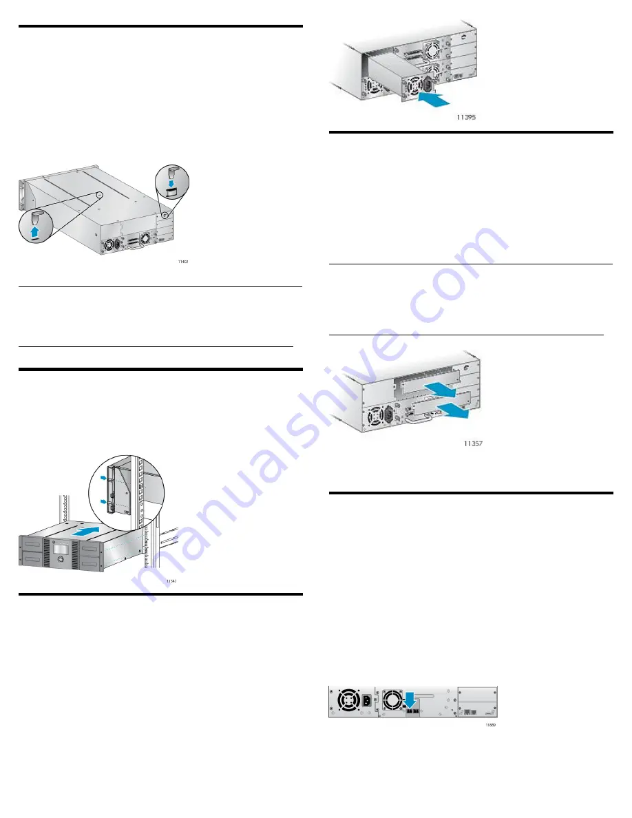
The shipping lock protects the robotic transport mechanism from
moving during shipment and must be removed and stored before
powering on the Library.
Locate the adhesive tape holding the storage lock at the top of the
Library. Remove the adhesive tape, then remove the storage lock and
store it as shown.
IMPORTANT:
The shipping lock must be removed for the robotics to work
properly. A robot move error is displayed if the shipping lock is not
removed.
2 Installing a rail kit
Install the rail kit using the instructions that shipped with the rail kit.
Install the Library in the rails. To secure the Library to the rails, tighten
the two captive screws in the Library bezel.
Optional: Adding a power supply
With the redundant power supply upgrade kit, the Library will continue
to operate without interruption if either power supply fails.
To install the redundant power supply, remove the cover plate for the
redundant power supply with a #2 Phillips screwdriver. Slide the power
supply into the bay until it is firmly seated. Tighten the three blue
thumbscrews with your fingers to secure the power supply.
3 Installing tape drives
The Library can hold up to two full-height or up to four half-height
drives. If the Library will only have one tape drive, install it in the
bottom drive bay. (Tape drives are numbered from the bottom up.)
Add the new tape drive directly above the currently installed tape
drive. Remove one drive bay cover for a half-height tape drive or two
drive bay covers for a full-height tape drive.
NOTE:
The Library will not operate with a full-height tape drive installed
in the second and third half-height drive bays. Install a full-height
tape drive either in the bottom two drive bays or the top two drive
bays.
Slide the tape drive into the bay until it is firmly seated. Tighten the
blue thumbscrews with your fingers to secure the tape drive.
4a Planning the FC configuration
The FC tape drive has two FC ports. Only one port may be used at a
time, but both ports can be connected for path failover if your
application supports path failover.
Direct connection
You will need a 2 Gb or 4 Gb FC HBA. A 4 Gb HBA is recommended
LTO-4 tape drive for optimum performance.
SAN connection
All switches between the host and the Library must be of the
appropriate type. A 2 Gb switch in the path may result in performance
degradation when backing up highly compressible data to a 4 Gb tape
drive.
Configure zoning on the Fibre switch so only the backup servers can
access the Library.
Page 4
Summary of Contents for NEO 400S
Page 10: ...OCP menu Page 10...


