Interface Descriptions :
•
SCSI Terminator - Used to terminate the last unit in a Daisy Chain.
•
SCSI-2 - Ultra 2 / Wide LVD uses high-density 68 pin connectors.
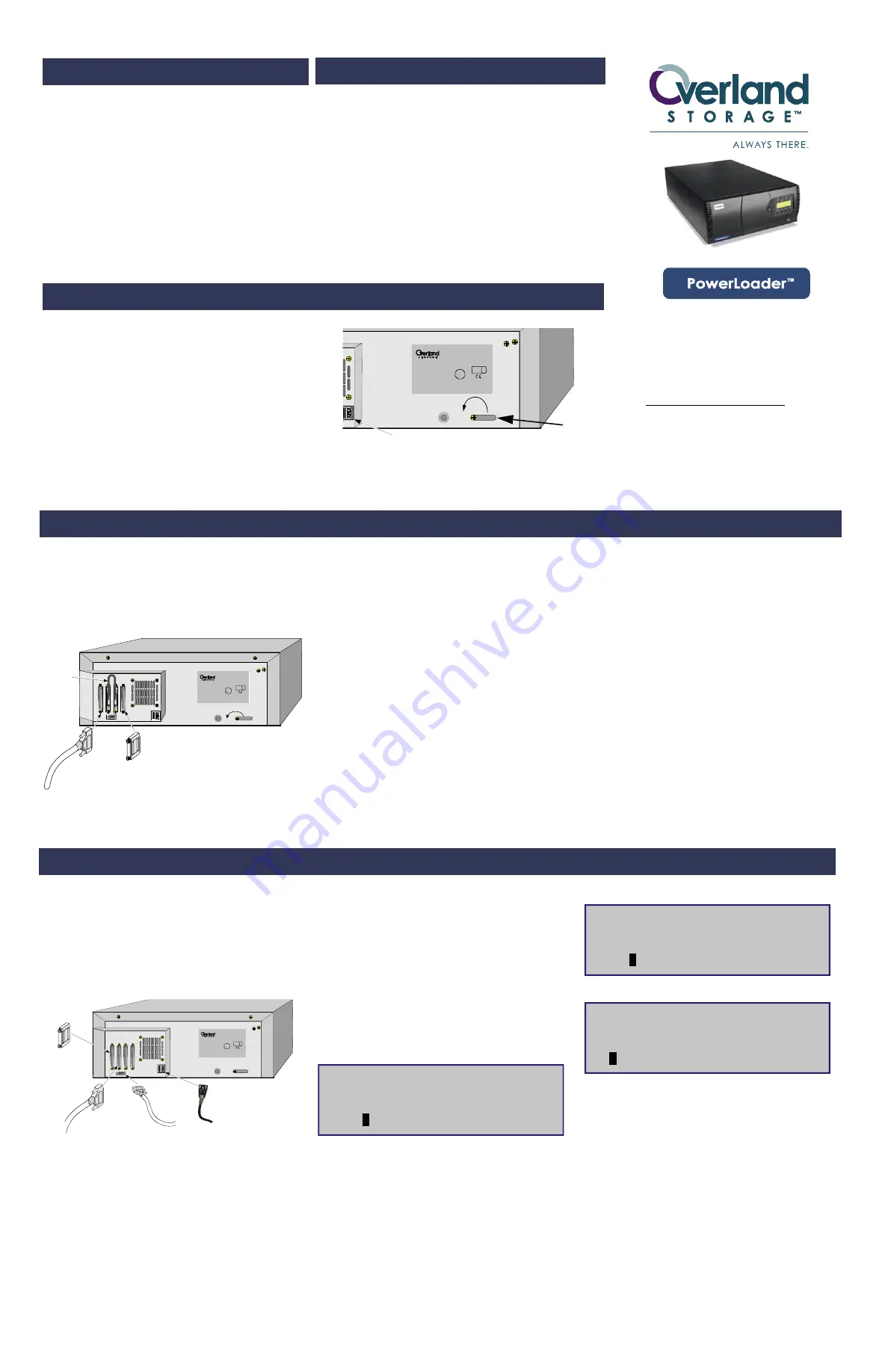
Single Host configurationdepicted below:
All SCSI cables used with the PowerLoader should meet the following
requirements:
LXM-0001
MODEL XXX-LXM-XXXXXX
P/N 000000-001/E
SERIAL NO 2B00174316
RATING
CAUTION
XXXXXXXXXXXXXXXXXXX
XXXXXXXXXXXXXXXXXXX
XXXXXXXXXXXXXXXX
This device complies with Part 15 of FCC rules Operation is
xxxxxxxxxxxxxxxxxxxxxxxxxxxxxxxxxxxxxxxxxxxxxxxxxxxxxxxxxxxxxxxxxxxx
xxxxxxxxxxxxxxxxxxxxxxxxxxxxxxxxxxxxxxxxxxxxxxxxxxxxxxxxxxxxxxxxxxxx
xxxxxxxxxxxxxxxxxxxxxxxxxxxxxxxxxxxxxxxxxxxxxxxxxxxxxxxxxxxxxxxxxxxx
C
L
U
R
US
TUV
PRODUCT SE RV ICES
S
G
xxxxxxxxxxxxxxxxxxxxxxxxxxxxxxxxxxxxxxxxxxxxxxxxxxxxxxxxxxxxxxxxxxxx
xxxxxxxxxxxxxxxxxxxxxxxxxxxxxxxxxxxxxxxxxxxxxxxxxxxxxxxxxxxxxxxxxxxx
xxxxxxxxxxxxxxxxxxxxxxxxxxxxxxxxxxxxxxxxxxxxxxxxxxxxxxxxxxxxxxxxxxx
X XXX XX XXX XX XXX XX XXX XX XXX XX XXX XX XXX XX XXX XX XXX XX XX XXX XX XXX XX XXX XX XXX XX
X XXX XX XXX XX XXX XX XXX XX XXX XX XXX XX XXX XX XXX XX XXX XX XX XXX XX XXX XX XXX XX XXX XX
X XXX XX XXX XX XXX XX XXX XX XXX XX XXX XX XXX XX XXX XX XXX XX XX XXX XX XXX XX XXX XX XXX X
INFORMA TION TE CHNOLOGY EQUIPMENT
SCSI
TERMINATOR
To Host
SHIP
RUN
Daisy Chain
MODEL XXX-LXM-XXXXXX
P/N 000000-001/E
SERIAL NO 2B00174316
RATING
CAUTION
XXXXXXXXXXXXXXXXXXX
XXXXXXXXXXXXXXXXXXX
XXXXXXXXXXXXXXXX
Thi s dev ice complies wi th Part 15 of FC C rules Operati on is
xxxx xxxxxxxx xxxxxxxx xxxxxxx xxxxxxxx xxxxxxxx xxxxxxxx xxxxxxx xxxxxxxx xx
xxxx xxxxxxxx xxxxxxxx xxxxxxx xxxxxxxx xxxxxxxx xxxxxxxx xxxxxxx xxxxxxxx xx
xxxx xxxxxxxx xxxxxxxx xxxxxxx xxxxxxxx xxxxxxxx xxxxxxxx xxxxxxx xxxxxxxx xx
C
L
U
R
US
TUV
P ROD U C T S ER V IC E S
S
G
xxxx xxxxxxxx xxxxxxxx xxxxxxx xxxxxxxx xxxxxxxx xxxxxxxx xxxxxxx xxxxxxxx xx
xxxx xxxxxxxx xxxxxxxx xxxxxxx xxxxxxxx xxxxxxxx xxxxxxxx xxxxxxx xxxxxxxx xx
xxxx xxxxxxxx xxxxxxxx xxxxxxx xxxxxxxx xxxxxxxx xxxxxxxx xxxxxxx xxxxxxxx x
X XX X XX XX X XX X XX X XX X XX XX X XX X XX X XX X XX XX X XX X XX X XX X XX XX X XX X XX X XX X XX XX X XX X
X XX X XX XX X XX X XX X XX X XX XX X XX X XX X XX X XX XX X XX X XX X XX X XX XX X XX X XX X XX X XX XX X XX X
X XX X XX XX X XX X XX X XX X XX XX X XX X XX X XX X XX XX X XX X XX X XX X XX XX X XX X XX X XX X XX XX X XX
•
Shielded or double-shielded, as required to meet EMI
specifications
•
Impedance match with cable terminators of 132 ohms
•
Characteristic impedance between 90 and 132 ohms (required)
•
34-pair twisted-pair
•
Each end of twisted pair ground must be connected to chassis
ground
•
When calculating the overall length of the bus, be sure to include
the internal cabling of the module, which is 27 inches (69 cm.) for
all models
•
Cables of different impedance should not be used together
*For additional specifications, refer to ANSI X3.131-1994 or later.
NOTE:
This equipment has been tested for
electromagnetic emissions and immunity using good
quality shielded cables. If you use poor quality or
unshielded cables, they may not comply with national
and international rules.
Connecting the PowerLoader to a Host
Computer
1)
Verify that the following hardware/software are available:
This instruction describes installing your PowerLoader. It includes:
•
Unpacking and Setting Up
•
Interfaces
•
Interface Cable Specifications
•
Connecting to the Host
•
Connecting to the Power Source
•
Rack Mount Installation
•
Configuration
a. Drives and the controller (library) are daisy-chained together
b. The host system has a compatible SCSI controller and the
appropriate driver software installed. (If you have questions
about installation for specific host systems, call your Technical
Support representative.)
c. The cables you are using meet the required specifications for type
and length
d. The terminator type matches your system.
2)
If the PowerLoader is the only SCSI device you are connecting to the
host, do the following:
a. Connect the cable from the host to one of the SCSI connectors
b. Attach the terminator to the outgoing SCSI connector
3)
If the PowerLoader is one of several units you are connecting to the host,
connect them in a daisy-chain by doing the following:
•
Connect the cable from the host, to one of the SCSI connectors of the
first SCSI device
•
Connect another cable from an unused connector of the first device to
an unused connector of the second SCSI device, and so on. You can
connect them in any order
NOTE:
The Default Screen displays a magazine with a
cartridge in slot 1.
1)
Press Enter to display the Main Menu:
SDLT1: No Tape
Loader Idle
1
X
_ _ _ _ _ _ _ _ _ _ _ _ _ _
W
15
SDLT2: No Tape
LTO 1: No Tape
Loader Idle
1
X
_ _ _ _ _ _ _ _ _ _ _ _ _ _ _ _
W
LTO 2: No Tape
•
MODEL XXX-LXM-XXXXXX
P/N 000000-001/E
SERIAL NO 2B00174316
RATING
CAUTION
XXXXXXXXXXXXXXXXXXX
XXXXXXXXXXXXXXXXXXX
XXXXXXXXXXXXXXXX
This dev ice complies wi th Part 15 of FCC ru les Operati on i s
xxxx xxxxxxxx xxxxxxxx xxxxxxx xxxxxxxx xxxxxxxx xxxxxxxx xxxxxxx xxxxxxxx xx
xxxx xxxxxxxx xxxxxxxx xxxxxxx xxxxxxxx xxxxxxxx xxxxxxxx xxxxxxx xxxxxxxx xx
xxxx xxxxxxxx xxxxxxxx xxxxxxx xxxxxxxx xxxxxxxx xxxxxxxx xxxxxxx xxxxxxxx xx
C
L
U
R
US
TUV
P RO D U C T S ER V IC E S
S
G
xxxx xxxxxxxx xxxxxxxx xxxxxxx xxxxxxxx xxxxxxxx xxxxxxxx xxxxxxx xxxxxxxx xx
xxxx xxxxxxxx xxxxxxxx xxxxxxx xxxxxxxx xxxxxxxx xxxxxxxx xxxxxxx xxxxxxxx xx
xxxx xxxxxxxx xxxxxxxx xxxxxxx xxxxxxxx xxxxxxxx xxxxxxxx xxxxxxx xxxxxxxx x
X XX X XX XX X XX X XX X XX X XX XX X XX X XX X XX X XX XX X XX X XX X XX X XX XX X XX X XX X XX X XX XX X XX X
X XX X XX XX X XX X XX X XX X XX XX X XX X XX X XX X XX XX X XX X XX X XX X XX XX X XX X XX X XX X XX XX X XX X
X XX X XX XX X XX X XX X XX X XX XX X XX X XX X XX X XX XX X XX X XX X XX X XX XX X XX X XX X XX X XX XX X XX
SHIP
RUN
Visually inspect the shipping containers and notify your carrier immediately of any
damage. Verify the contents against the packing list. If parts are missing or the
equipment is damaged, notify your representative. Always save the containers and
packing materials for any future reshipment.
To set up the PowerLoader, do the following:
•
Follow the directions in the shipping container to unpack the PowerLoader.
•
Save the packing materials in case you need to return the unit for repairs.
•
You do not have to assemble anything.
Place the PowerLoader on a stable horizontal surface with at least a 2-inch clearance
behind the chassis to allow sufficient cooling air to flow freely from the fan, or mount
your unit in an equipment rack using the Rack Mount Installation section found in the
User and Installation Manual or Rack Mount Quick Install card.
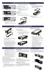
NOTE:
You must unpark the shuttle before installation and
park the shuttle before shipping.
Parking the Shuttle
1)
Make sure the power cord is disconnected from line power.
2)
Locate the shuttle retention clip on the back of the unit.
3)
Turn the clip to the RUN position by pulling it away from the back of the
unit and rotating it clockwise 180 degrees. Follow the arrow on the back of
the unit.
4)
Release the clip, allowing it to fit into the stow slot.
Parking the Shuttle
1)
Make sure the power cord is disconnected from line power.
2)
Locate the shuttle retention clip on the back of the unit.
3)
Turn the clip to the SHIP position by pulling it away from the back of the
unit and rotating it counterclockwise 180 degrees. Follow the arrow on the
back of the unit.
4)
Release the clip, allowing it to fit into the center of the leadscrew bearing.
Installing the PowerLoader (continued)
Configure the PowerLoader
You can change configuration option settings if necessary from the Control
Panel. Before changing any settings, refer to your host system
documentation or contact your Technical Support representative.
The SCSI defaults are: parity on; DLT1 Bus ID = 4; DLT2 Bus ID = 5;
Library Bus ID = 6.
Configuration Example – Setting SCSI ID
Turn the module on, and wait until the Power-On Self Test (POST) concludes
and the Default Screen displays:
DLT1: No Tape
Loader Idle
1
X
_ _ _ _ _ _ _ _ _ _ _ _ _ _
W
15
DLT2: No Tape
•
Attach the terminator to last unused SCSI connector of the last
device in the chain
4)
If the PowerLoader is connected to 2 hosts at the same time:
•
In the two-host configuration, a separate SCSI bus runs from each
host to a different drive. As shown in the following illustration, each
incoming SCSI bus attaches to the left connector of each pair. Place a
terminator at the right connector of each pair.
Connect to the Power Source
The AC power cable is a standard grounding AC cable, which attaches to an
IEC-compatible connector on the rear panel. Connect the cable to the
connector on the module, and connect the other end to a reliably grounded
AC outlet or rack power outlet.
To maintain product safety compliance, use a power cord with a suitable
electrical rating, UL Listed (USA), CSA Certified (Canada), or Harmonized
marked <Har> or nationally certified, (Europe).
MODEL XXX-LXM-XXXXXX
P/N 000000-001/E
SERIAL NO 2B00174316
RATING
CAUTION
XXXXXXXXXXXXXXXXXXX
XXXXXXXXXXXXXXXXXXX
XXXXXXXXXXXXXXXX
This dev ice comp lie s with Part 15 of FCC rules Op eration is
xxxx xxxxxxxx xxxxxxxx xxxxxxx xxxxxxxx xxxxxxxx xxxxxxxx xxxxxxx xxxxxxxx xx
xxxx xxxxxxxx xxxxxxxx xxxxxxx xxxxxxxx xxxxxxxx xxxxxxxx xxxxxxx xxxxxxxx xx
xxxx xxxxxxxx xxxxxxxx xxxxxxx xxxxxxxx xxxxxxxx xxxxxxxx xxxxxxx xxxxxxxx xx
C
L
U
R
US
TUV
P RO D U C T S ER V IC E S
S
G
xxxx xxxxxxxx xxxxxxxx xxxxxxx xxxxxxxx xxxxxxxx xxxxxxxx xxxxxxx xxxxxxxx xx
xxxx xxxxxxxx xxxxxxxx xxxxxxx xxxxxxxx xxxxxxxx xxxxxxxx xxxxxxx xxxxxxxx xx
xxxx xxxxxxxx xxxxxxxx xxxxxxx xxxxxxxx xxxxxxxx xxxxxxxx xxxxxxx xxxxxxxx x
X XX X XX XX X XX X XX X XX X XX XX X XX X XX X XX X XX XX X XX X XX X XX X XX XX X XX X XX X XX X XX XX X XX X
X XX X XX XX X XX X XX X XX X XX XX X XX X XX X XX X XX XX X XX X XX X XX X XX XX X XX X XX X XX X XX XX X XX X
X XX X XX XX X XX X XX X XX X XX XX X XX X XX X XX X XX XX X XX X XX X XX X XX XX X XX X XX X XX X XX XX X XX
SCSI
TERMINATOR
SCSI
CONNECTOR
DIAGNOSTIC
CONNECTOR
POWER
CONNECTOR
LXM-0014
DIAGNOSTIC
Unparking & Parking the Shuttle
Instruction Contents
Unpacking the Unit
Installing the PowerLoader
Getting Help
You can get support via the Internet at
www.overlandstorage.com
, or call
Tech Support at 800 729-8725 Option 5
©2004 Overland Storage, Inc.
(Mar 2004)
Part Number 104245-104 Rev A
Installation Instruction