background image

Technical Data

313221M

59

Summary of Contents for 313221M

Page 1: ...approvals and maximum working pressures For patent information see www graco com patents EnergyComplete Sprayer Manual No For use with EnergyComplete Air Infiltration Barrier with Flexible Seal Techn...

Page 2: ...mpressor Power Switch Circuit Breaker 11 Air Compressor Controls 11 Setup 12 Preheat Hoses 17 Startup 18 Spraying Dispensing 19 Pause 20 Pressure Relief Procedure 21 Shutdown 21 Maintenance 22 Flushin...

Page 3: ...nerwithpink com EnergyComplete Spray Gun Part No Description 313294 Instruction Parts Manual A Side Displacement Pump White Material Part No Description 313123 Instruction Parts Manual B Side Displace...

Page 4: ...Electrical Connection Package Description Maximum Working Pressure psi MPa bar Maximum Air Working Pressure psi MPa bar 257125 257089 120 V 15 A cord motor 15 A cord heaters Heated EnergyCom plete Sp...

Page 5: ...fluids you are using Store hazardous fluid in approved containers and dispose of it according to applicable guide lines PERSONAL PROTECTIVE EQUIPMENT You must wear appropriate protective equipment whe...

Page 6: ...ressure Relief Procedure in this manual when equipment is not in use Do not exceed the maximum working pressure or temperature rating of the lowest rated system component See Technical Data in all equ...

Page 7: ...used to circulate full pails up to temperature Fast Recirculation Use to support higher flow rates or higher tempera tures by preheating the pails Agitates fluid within pails to avoid heating only the...

Page 8: ...K Control Panel see FIG 2 page 9 L Electric Motor and Drive Housings M Suction Tubes N Recirculation Tubes P Air Line outlet R Outlet Hose Connections S Recirculation Tube Connections T Fluid Tempera...

Page 9: ...A circuit breaker FIG 2 Controls and Indicators MP CF ST HP TD TD r_256765_313221_b_37 Icon Setting Function Stop Park Stops motor and automati cally parks pumps Slow Recirc Slow recirculation speed F...

Page 10: ...of com ponent A and B heaters Indicator lights HL turn on when thermostats are heating and off when heater reaches setpoint Fluid Temperature Sensors and Displays See FIG 2 Fluid temperature sensors...

Page 11: ...cuit Breaker Switch CP turns power on to compressor and regula tor The switch includes a 20 A circuit breaker Air Compressor Controls Pressure Gauge PG indicates set air pressure by reg ulator Regulat...

Page 12: ...uid hoses connected to a properly grounded Energy Complete Sprayer Do not operate without at least one grounded fluid hose Object being sprayed follow your local code Solvent pails used when flushing...

Page 13: ...A each Three NEMA 5 15T Two NEMA 5 15T Table 3 Extension Cord Requirements Required Wire Size Up to 100 ft 30 m AWG 12 Cords must be 3 conductor grounded rated for your environment FIG 5 Use Three Sep...

Page 14: ...he coupler to the gun air fitting For sprayers without a compressor connect the main air supply to the quick disconnect fitting on the air filter behind the front brace Air supply hose must be at leas...

Page 15: ...ed materials in the pail Material left in the pails overnight may need to be remixed Fill wet cups through slots in plate or loosen screws and swing plate aside Pump rod and connecting rod move during...

Page 16: ...b to Stop Park c Plug in power cord s See TABLE 2 page 13 A B G r_256765_313221_b_18 N A B W r_256765_313221_b_19 d Turn on Motor Power e Set Recirc Spray valves to Recirc f Set function knob to Slow...

Page 17: ...te circulation lines CL back to red and white fluid pails 1 Remove block 702 Install circulation manifold 701 on gun fluid manifold GM Open all valves in the fluid circuit 2 Perform Startup page 18 3...

Page 18: ...ent to cool completely before touch ing it Wear gloves if fluid temperature exceeds 110 F 43 C 1 Perform Setup pages 12 16 2 Set function knob to Slow Recirc or Fast Recirc 3 Turn on Heater Power 4 Te...

Page 19: ...ow balanced pressures The pressure imbalance alarm Status Code 1 is inactive for 10 sec after entering spray pres sure mode to allow time to balance pressures Watch gauges for 10 sec to be sure pressu...

Page 20: ...gage piston safety lock 2 Set function knob to Slow Recirc 3 Set Recirc Spray valves to Recirc until tempera ture readouts come back up 4 If you stop spraying for more than 2 minutes when using an imp...

Page 21: ...s more than 10 minutes use the following procedure If you will be shut down for more than 3 days first see Flushing page 23 1 Follow all steps of Pressure Relief Procedure at left 2 If using an imping...

Page 22: ...may settle out over time If using an impingement mix gun close gun fluid valves A and B when not spraying Doing this will keep the internal parts of the gun cleaner and pre vent crossover Clean gun m...

Page 23: ...mmable solvents See compatible sol vents on page 7 1 Engage piston safety lock Close fluid valves A and B Leave air on 2 Set function knob to Stop Park 3 Shut off Heater Power Allow system to cool 4 R...

Page 24: ...s for thorough cleaning with sol vent Turn Recirc Spray valve A to Spray Open gun into waste container A Set function knob to Slow Recirc until hose is flushed Set function knob to Stop Park Repeat fo...

Page 25: ...ssary 2 Reduce pressure of higher component by slightly turning Recirc Spray valve for that component toward Recirc until gauges show balanced pres sures 3 Check fluid inlet strainers 51a page 22 and...

Page 26: ...and 2 Settings DIP Switch and Function Left Right DIP Switch 1 If selected causes shutdown or displays a warning if there is a pressure imbalance exceeds selection made in DIP Switch 2 WARNING SHUTDOW...

Page 27: ...ing operation 1 Locked rotor motor unable to turn Replace motor page 43 2 Short on control board Replace board page 38 3 Worn or hung up motor brush causing arcing of brush at commutator Replace brush...

Page 28: ...e movement Shorted armature Replace motor page 43 Check motor commutator for burn spots black pitting or other damage Remove motor Have motor shop resurface commutator or replace motor page 43 Failed...

Page 29: ...s normal Component B is typi cally higher viscosity than component A until the material is heated during recirculation No action required One gauge shows half as many pulses as the other when pumps ar...

Page 30: ...light is off Heater Power shut off or circuit breaker tripped Cycle Heater Power off then on to reset circuit breaker Bad thermostat With power on check for continuity at clicks of heater control knob...

Page 31: ...f valve until it locks in place at 100 psi Air compressor does not run Power is not on Turn compressor power on Voltage to compressor below 105 Vac for 120 Vac Try another outlet Reduce extension cord...

Page 32: ...cian connect power and ground to main power switch terminals see page 12 Be sure to shut off all power to the equipment before repairing 1 Flush if possible see page 23 If not possible clean all parts...

Page 33: ...and gasket 503b are positioned inside each valve cartridge 503 3 Apply PTFE pipe sealant to all tapered pipe threads before reassembling 4 Reassemble in reverse order following all notes in FIG 8 FIG...

Page 34: ...information in pump manual which is supplied with your unit Use dropcloth or rags to protect EnergyCom plete Sprayer and surrounding area from spills 1 See Before Beginning Repair page 32 Relieve pre...

Page 35: ...discon nect steel outlet tube 16 from heater inlet 5 Remove pump rod cover 222 Push clip up in back and push pin 217 out Loosen locknut 218 by hit ting firmly right to left with a non sparking hammer...

Page 36: ...osen setscrew 65 on thermowell housing 64 See FIG 10 on page 36 b Pull sensor 424 out of thermowell housing c Work sensor and wire out of cable channel 3 Remove access cover 8 from back of control mod...

Page 37: ...and detent plate 415 6 Install new potentiometer 404 in reverse order Position potentiometer so slot S is horizontal Posi tion knob 416 so pointer P faces up Install knob on shaft so slot S engages al...

Page 38: ...ff Status code motor not running LED blinks status code Check motor before replacing board See Elec tric Motor page 43 1 See Before Beginning Repair page 32 Relieve pressure page 21 Apply thermal comp...

Page 39: ...Cable Red Black Yellow Yellow Red Black Black White Jumper 1 2 3 4 5 6 7 8 9 10 J15 J14 J3 J8 J2 Black Red White Pressure Transducer A Pressure Transducer B CONTROL BOARD 249434 120 V 249432 240 V Bla...

Page 40: ...ts 5 Install o ring 89 on new transducer 80 FIG 13 6 Install transducer in heater or manifold Mark board end of cable with tape red transducer A blue transducer B 7 Route cable through channel to cont...

Page 41: ...bell MB 5 Push drive housing 215 onto motor 201 Install screws 220 6 Install drive housing covers 221 on A side 227 on B side and screws 207 Pumps must be in phase both at same position in stroke 1 S...

Page 42: ...h switch on B side TI7028a 223 0 6 in 15 2 mm from inside edge 1 0 in 25 4 mm from inside bottom edge FIG 14 Drive Housing Crankshaft must be in line with crankshaft at other end of motor so pumps mov...

Page 43: ...7 d Unplug cable 37 from fan 202 See FIG 22 on page 46 e Thread motor power switch harness out bottom of control module and cable channel to free motor 5 Remove screws holding motor to bracket Lift mo...

Page 44: ...rom regulator 123 See FIG 16 4 Remove four nuts 138 and control panel 104 5 Disconnect power leads PL from power switch under control panel 104 and disconnect air outlet tube 114 To repair compressor...

Page 45: ...s 75 Pull out bolts 77 from cart 1 and remove front brace 28 10 Remove four screws 140 and front panel 103 from unit 11 Disconnect fan electrical connection 12 Remove nuts 120 bolts 119 to remove comp...

Page 46: ...rews holding fan to shield 206 Install new fan in reverse order 3 If voltage is not correct check fan cable connection at J9 on control board see FIG 12 page 39 Replace brushes worn to less than 1 2 i...

Page 47: ...51 153 153 154 154 Ref Part Description Qty 151 257089 PROPORTIONER heated 120V 15 A see page 48 257125 only 1 256765 PROPORTIONER heated 120V 15 A see page 48 257126 only 1 152 256998 GUN 1 153 25709...

Page 48: ...Heaters and Compressor 21 20 19 17 18 13 2 76 70 27 25 26 25 23 23 24 10 40 14 12 55 5 60 57 11 8 3 32 33 7 1 81 15 73 71 74 75 12 31 5 29 58 59 53 77 28 3 36 3 56 62 61 6 63 91 54 91 72 16 68 Model...

Page 49: ...ER air 3 8 auto drain 1 32 15G719 LABEL status codes 1 33 15G280 LABEL warning 1 36 190774 BLANK label kit 1 37 15G458 CABLE fan 46 in w plug board connection 2 38 24K995 CORD SET power 125V 2 40 1034...

Page 50: ...113 106 See compressor wiring diagram on page 51 120 124 148 116 110 115 114 128 150 149 138 142 102 140 116 151 107 118 117 121 109 134 135 137 125 104 105 131 133 129 130 143 143 132 132 130 123 r_2...

Page 51: ...ps hex hd 1 118 114421 BUSHING strain relief 1 119 113956 BOLT carriage 2 120 112958 NUT hex flanged 2 121 113802 SCREW hex hd flanged 1 123 115242 REGULATOR air 1 4 npt 1 124 24K985 FAN cooling 120 V...

Page 52: ...d 8 32 x 3 8 in 10 mm 12 208 116074 WASHER thrust steel 2 209 107434 BEARING thrust bronze 2 210 248231 CRANKSHAFT KIT 2 211 180131 BEARING thrust bronze 2 212 116073 WASHER thrust steel 2 213 116079...

Page 53: ...R 1 405 119930 INDICATOR status LED 1 406 249434 BOARD control 120 V units only 1 407 15G230 CABLE harness 1 408 107156 SCREW machine pan hd 7 409 113505 NUT keps hex hd 10 410 119898 BULKHEAD FITTING...

Page 54: ...lve drain 2 506 111600 PIN grooved 2 507 111763 FITTING elbow 1 4 npt 2 509 166863 ADAPTER 3 8 npt x 1 4 npt 1 510 162453 NIPPLE 1 4 npsm x 1 4 npt 3 511 512351 FITTING adapter 2 512 16C786 MANIFOLD f...

Page 55: ...Part Description Qty 801 HOSE coupled 1 4 in x 6 ft 1 802 HOSE coupled 1 4 in x 6 ft 1 803 HOSE air 6 ft 1 4 in ID 1 804 TAPE electrical 1 805 103473 STRAP tie wire 4 Ref Part Description Qty 801 HOSE...

Page 56: ...manual 313123 257344 PUMP displacement red see manual 313383 257349 KIT repair pump white 257348 KIT repair pump red 256779 KIT repair compressor 246385 STRAINER 24K981 DISPLAY temperature with sensor...

Page 57: ...Dimensions 313221M 57 Dimensions 21 25 in 539 75 mm 43 5 in 1105 mm 27 in 685 8 mm r_256765_313221_b_4 EnergyComplete Sprayer 256765 257089 Weight 190 lb 86 kg 130 lb 59 kg...

Page 58: ...Output per Cycle B side red fluid 00044 gal 0016 liter Overpressure Relief Recirc Spray valves automatically relieve excessive fluid pressure back to supply pails Heater Power 120V models 850 W each...

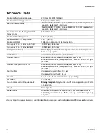
Page 59: ...Technical Data 313221M 59...

Page 60: ...isclose any defect in material or workmanship repairs will be made at a reasonable charge which charges may include the costs of parts labor and transportation THIS WARRANTY IS EXCLUSIVE AND IS IN LIE...

Reviews: