background image

4.Quick Start


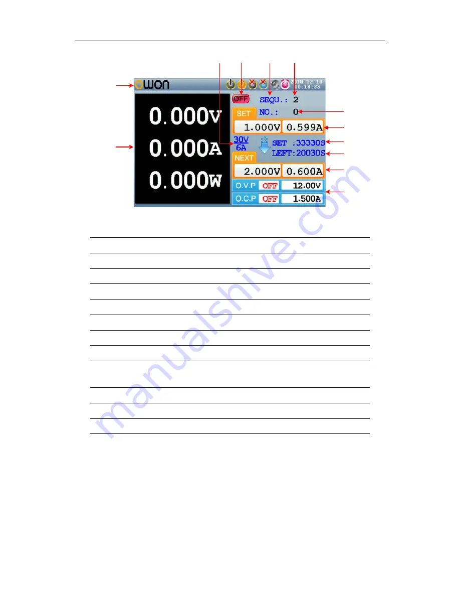
Figure 4-4 User interface in Parallel/Series mode 


① 

Maximum ratings of voltage and current 

② 

Channel status   

③ 

Output mode of timing output (Sequence


/ Loop) 

④ 

Timer range 

⑤ 

The parameter number of the current output when the timing output is on 

⑥ 

Specified values of voltage and current   

⑦ 

Specified time of current output when the timing output of is on   

⑧ 

Left time of current output when the timing output of is on   

⑨ 

Specified values of voltage and current that will be output at the next fixed 
times when the timing output of is on 

⑩ 

Status and set values of O.V.P and O.C.P in current status 

⑪ 

Actual output values of voltage , current and power 

⑫ 

Status icons, see "

Status Icons

" on P10 for more details 


z


Plus-minus Mode


9

Summary of Contents for ODP3032

Page 1: ...ODP Series Linear Programmable DC Power Supply User Manual ODP3032 ODP3052 WWW OWON COM WWW OWON COM HK WWW OWON COM CN ...

Page 2: ...nue to improve products and reserves the rights to changes specification at any time without notice OWON is the registered trademark of the Lilliput Company Headquarter Fujian Lilliput Optoelectronics Technology Co Ltd The mansion of optoelectronics 19 Heming Road Lantian industrial zone Zhangzhou Fujian China Tel 86 596 2130430 Fax 86 596 2109272 Web www owon com hk Mail Business Consulting sales...

Page 3: ... not apply to any defect failure or damage caused by improper use or improper or inadequate maintenance and care Lilliput shall not be obligated to furnish service under this warranty a to repair damage resulting from attempts by personnel other than Lilliput representatives to install repair or service the product b to repair damage resulting from improper use or connection to incompatible equipm...

Page 4: ...pection 12 4 4 2 Current Output Inspection 12 4 5 Working Mode 13 4 5 1 Icons and Ratings 13 4 5 2 Connections 13 4 6 System Menu Operation 14 5 Front Panel Operation 15 5 1 Turn On Off the Channel Output 16 5 2 Set the Output Voltage Current 16 5 3 Over Voltage Current Protection 17 5 3 1 Set O V P 17 5 3 2 Set O C P 18 5 4 Timing Output 18 5 4 1 Enter Exit Timer Status 18 5 4 2 Timer Setting 18 ...

Page 5: ...ime 21 5 6 4 Set System Time 22 5 6 5 Buzzer 22 5 6 6 View System Information 22 5 6 7 Set as Default 22 5 7 Use Built in Help 23 6 Communication with PC 24 7 Troubleshooting 25 8 Technical Specifications 26 9 Appendix 28 9 1 Appendix A Enclosure 28 9 2 Appendix B General Care and Cleaning 28 ...

Page 6: ...user s manual for more information about ratings before connecting to the instrument Do not operate without covers Do not operate the instrument with covers or panels removed Use Proper Fuse Use only the specified type and rating fuse for this instrument Avoid exposed circuit Do not touch exposed junctions and components when the instrument is powered Do not operate if in any doubt If you suspect ...

Page 7: ... damage to this product or other property Terms on the Product The following terms may appear on this product Danger It indicates an injury or hazard may immediately happen Warning It indicates an injury or hazard may be accessible potentially Caution It indicates a potential damage to the instrument or other property might occur Safety Symbols Symbols on the Product The following symbol may appea...

Page 8: ...e and panel layout and variety standard interfaces to meet diverse test requirements Features and benefits Dual Independent Separate Control Outputs Outstanding line regulation rate 0 01 2mV voltage 0 01 1mA current Outstanding load regulation rate 0 01 3mV voltage 0 2 3mA current Low ripples noise 300 μVrms 2 mVpp Four operating mode independent parallel connection series connection plus minus Up...

Page 9: ...owing topics mainly z Front Rear Panel Overview z User Interface Overview z How to Implement General Inspection z How to Implement Power On Check z How to Implement Output Inspection z Instruction of the four Working Mode z Instruction of the System Menu Operation 4 ...

Page 10: ...c keys decimal point and backspace key Up and down direction key Select menu or change the parameter Enter key Enter menu or confirm the parameter entered Knob Select menu or change the parameter pressing it has the same effect as pressing the enter key Left and right direction key Select menu or move the cursor System key Enter the system menu Timer key Enter exit timer status Help key View the b...

Page 11: ...ange Curr CC key Set the output current of Channel 1 Orange ON OFF key Enable disable the output of Channel 1 Function keys Record key Record the current output data as a txt file and save to USB disk Recall key Recall the stored settings file Save key Save the current setting parameters Set key Enter exit the setting interface of timing output Instructions for panel key indicator ON OFF key The i...

Page 12: ...evice such as connect the instrument to a PC COM port Connect the instrument with external equipment as serial port Power socket AC input connector Fuse Use the specified fuse according to the voltage scale Power switch Switch between 110V and 220V Fan Fan inlet 4 1 3 User Interface The below figures are the interfaces in Timer status you can consult the following instructions for the interfaces i...

Page 13: ...ue of power for Channel 1 Timing output mode of Channel 1 Sequence Loop Timer range of Channel 1 The parameter number of the current output when the timing output of Channel 1 is on Set values of voltage and current for Channel 1 Actual output values of voltage and current for Channel 1 Status and set values of O V P and O C P for Channel 1 in current status Status icons see Status Icons on P10 fo...

Page 14: ...d values of voltage and current Specified time of current output when the timing output of is on Left time of current output when the timing output of is on Specified values of voltage and current that will be output at the next fixed times when the timing output of is on Status and set values of O V P and O C P in current status Actual output values of voltage current and power Status icons see S...

Page 15: ...of Negative same as Positive The parameter number of the current output when the timing output of Negative is on same as Positive Set values of voltage and current for Negative Actual output values of voltage and current for Negative Status and set values of O V P and O C P for Negative in current status Status icons see Status Icons on P10 for more details Status Icons Icons Instruction Connect a...

Page 16: ...ription If it is found that there is any accessory lost or damaged please get in touch with the distributor of Lilliput responsible for this service or the Lilliput s local offices 3 Check the Complete Instrument If it is found that there is damage to the appearance of the instrument or the instrument can not work normally or fails in the performance test please get in touch with the Lilliput s di...

Page 17: ... operation from the front panel For the procedures below it is suggested that you read Working Mode on P13 Turn On Off the Channel Output on P16 and Set the Output Voltage Current on P16 4 4 1 Voltage Output Inspection The following steps verify basic voltage functions without load 1 When the instrument is under no load power on it make sure that the output current setting value of each working mo...

Page 18: ...ries are designed with four working modes Independent Parallel Series and Plus minus Press the Mode key to switch between the four working modes For the instructions of the user interfaces in the four working mode please see User Interface on P7 4 5 1 Icons and Ratings The status icons and voltage current ratings of the four mode is listed below Independent Parallel Series Plus minus Status Icons ...

Page 19: ... one of the direction key the key or the knob to enter the submenu to return to main menu press the direction key z In the submenu press direction key or turn the knob to move around the submenu items 3 Enter the menu Press the key or the knob to enter the selected menu item 4 Exit the menu Press System key to close the menu or the pop up box Note In this document System CH1 O V P means Enter the ...

Page 20: ... chapter will deal with the following topics mainly z How to Turn On Off the Channel Output z Set the Output Voltage Current z Over Voltage Current Protection z Timing Output z Save Recall Record Functions z System Settings z How to Use Built in Help 15 ...

Page 21: ... 1 Press the orange Volt CV or Curr CC key the input box of Channel 1 output voltage current will pop up 2 The key light will start blinking indicating to input there are two methods to change the value Modify Turn the knob or press the direction key to change the value by the unit of cursor position hold down the direction key to change continuously Press the key to move the cursor Input Use the ...

Page 22: ...must be restarted to output normally This function can keep the power output from exceeding the load rating in order to protect the load The O V P O C P can be set separately for the four working mode and for different status normal timer You can enable or disable these functions as required The parameters of the O V P O C P set in normal status take effect in normal status The parameters of the O...

Page 23: ...en ON or OFF the O C P in current mode and status is enabled or disabled Note In Plus minus mode the O C P status of Positive and Negative will remain consistent you can set either of them The O C P value can be set separately 3 Use the numeric keys to enter the O C P value in current mode and status The maximum in Independent Series and Plus minus mode is 3 15A the maximum in Parallel mode is 6 3...

Page 24: ...ct the right parameter area Press the key to change the parameter item After selecting the parameter use the numeric keys to enter a desired value press the key to confirm Press the key to go to the previous or next setting page Note If the input value exceeds the rating of current working mode the system will change it to the maximum rating automatically after pressing the key to confirm In the P...

Page 25: ...er turning on the channel again will restart the timing output and the timer 5 5 Save Recall Record ODP Series support operations with a USB flash device and local file storage including store recall and delete current setting parameters The current data of the channel can be recorded into a txt file which stored in USB disk You can connect the USB disk to the USB Host interface in Figure 4 2 Afte...

Page 26: ...xt file which stored in USB disk 1 Press the Record key press the numeric keys to set the interval 2 Press the key to start recording During recording an icon is shown on the status bar 3 Press the Record key again to stop recording 5 6 System Settings You can set the system by operating the System Menu It is suggested that you should read the System Menu Operation on P14 first so as to be familia...

Page 27: ...bar 5 6 6 View System Information Press the System key and enter System SysInfo You can view the Serial Number Software Version and Hardware Version 5 6 7 Set as Default Press the System key and choose System Default press the key to use the factory defaults see table below Independent Plus minus Working Mode Parameter CH 1 CH 2 Parallel Series Negative Positive Voltage 5 V 5 V 12 V 15 V 12 V 12 V...

Page 28: ...ction button the catalog will display in the screen 2 Press the key or turn the knob to choose help topic 3 Press the key to view the details about the topic press the key to go back to the catalog 4 Press Help again to exit the help or just do other operations 23 ...

Page 29: ... rear panel of the Power Supply to the COM interface of a PC 3 Install the driver When the Power Supply is turned on a dialog will appear on the PC screen and guide you to install the USB driver The driver is in the USBDRV folder under the directory where the ODP communication software is installed such as C Program Files ODP USBDRV 4 Use the software Run the ODP software click the Menu button in ...

Page 30: ...tput is abnormal z Check if the output voltage is set to 0V If so set it to other value z Check if the output current is set to 0A If so set it to other value z When in timer status check if there is any voltage current value of timer setting is set to 0 If so set it to other value z If the problem still exists please contact Lilliput for our service 3 Cannot identify the USB device correctly z Ch...

Page 31: ...rallel 0 6A 3A Independent Series Plus minus 0 5A DC Output Ratings Current ODP3052 Parallel 0 10A 5A CV 0 01 2mV 3mV Line Regulation CC 0 01 1mA CV 0 01 3mV 0 1 3mV Load Regulation CC 0 2 3mA CV 300 μVrms 2 mVpp 300 μVrms 2 mVpp Noise and Ripple 20Hz 7MHz CC 3mArms Voltage 1mV None Settings Resolution Current 1mA None Voltage 0 05 1mV None Settings Accuracy 25 5 Current 0 1 1mA None Voltage 1mV 1...

Page 32: ...0 60Hz 110V 125 V F5A ODP3032 220V 250 V F3A 110V 125 V F10A Fuse ODP3052 220V 250 V F5A Environment Temperature Working temperature 0 40 Storage temperature 20 60 Relative Humidity 90 Height Operating 3 000 m Non operating 15 000 m Cooling Method Fan cooling Mechanical Specifications Dimension 298mm 202mm 450mm W H D Weight About 9 8 kg Interval Period of Adjustment One year is recommended for th...

Page 33: ... often as operating conditions require To clean the instrument exterior perform the following steps 1 Wipe the dust from the instrument surface with a soft cloth Do not make any scuffing on the transparent LCD protection screen when clean the LCD screen 2 Disconnect power before cleaning your instrument Clean the instrument with a wet soft cloth not dripping water It is recommended to scrub with s...

Reviews: