background image


SPE series Single Channel   

Output DC Power Supply 

User Manual   


For product support, visit : www.owon.com.hk/download 

Summary of Contents for SPE Series

Page 1: ...SPE series Single Channel Output DC Power Supply User Manual For product support visit www owon com hk download ...

Page 2: ...that in the materials published originally The information in this manual was correct at the time of printing However LILLIPUT will continue to improve products and reserves the rights to change specification at any time without notice is the registered trademark of the LILLIPUT Company Fujian LILLIPUT Optoelectronics Technology Co Ltd No 19 Heming Road Lantian Industrial Zone Zhangzhou 363005 P R...

Page 3: ... copy of the customers proof of purchase is also required This warranty shall not apply to any defect failure or damage caused by improper use or improper or inadequate maintenance and care We shall not be obligated to furnish service under this warranty a to repair damage resulting from attempts by personnel other than our company representatives to install repair or service the product b to repa...

Page 4: ... 4 Panel Operation 8 4 1 Turn On Off the Channel Output 8 4 2 Set the Output Voltage Current 8 4 3 Over Voltage Current Protection 8 4 4 Memory key shortcut settings 9 4 4 1 Quick output 9 4 4 2 Edit 9 4 5 Set List Waveform Output 10 4 5 1 List waveform editing 10 4 5 2 List waveform output 11 4 6 Set Automatic Output at Power on 12 4 7 Display 12 5 Troubleshooting 13 6 Appendix 14 6 1 Appendix A ...

Page 5: ... the user manual for more information about ratings before connecting to the instrument Do not operate without covers Do not operate the instrument with covers or panels removed Use the Proper Fuse Use only the specified type and rating fuse for this instrument Avoid exposed circuit Be careful when working on exposed circuitry to avoid risk of electric shock or other injury Do not operate if any d...

Page 6: ...es that could result in damage to this product or other property Terms on the product The following terms may appear on this product Danger Indicates an immediate hazard or injury possibility Warning Indicates a possible hazard or injury Caution Indicates potential damage to the instrument or other property Safety Symbols Symbols on the product The following symbols may appear on the product Hazar...

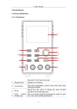
Page 7: ...ew 1 Display Area Display user interface 2 Current Key Set current parameters press to move the cursor when editing parameters 3 Knob Select the main menu or change the value function equals to the confirmation key 4 Over Current Setting Key Set over current protection parameters press to move the cursor when editing parameters ...

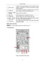
Page 8: ...t Terminal Output access of channel 8 USP Port USB charging port no read write function 9 Display Key Number display and curve display switch key 10 Over Voltage Setting Key Set over voltage protection parameters press to move the cursor when editing parameters 11 Voltage Key Set voltage parameters press to move the cursor when editing parameters Button light instruction On Off key The key lights ...

Page 9: ... output Set values of voltage Set values of current Set values of O V P Set values of O C P Figure 3 3 User Interface 3 2 General Inspection After you get a new power supply it is recommended that you should make a check on the instrument according to the following steps 1 Check whether there is any damage caused by transportation If it is found that the packaging carton or the foamed plastic prot...

Page 10: ... about it a repairing or replacement of the instrument will be arranged by us 3 3 Power Inspection 1 Use the power cord supplied with the accessories to connect the instrument to the AC power Warning To prevent electric shock make sure that the instrument is properly grounded 2 Press the power button on the front panel the button light will be on and the startup screen will be displayed on the scr...

Page 11: ...cross and output terminals with an insulated test lead on this channel Use a wire size sufficient to handle the maximum current 2 Set the output voltage to the maximum rating on this channel 3 Turn on the channel output Ensure the channel you used is in Constant Current output mode 4 Set some different current values on this channel check if the actual current value displayed is close to the set c...

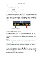
Page 12: ...otection Overvoltage protection O V P or overcurrent protection O C P after the output is turned on once the output voltage current reaches the set value of O V P O C P the instrument will cut off the output a warning will show on the screen Note When the instrument disables the output due to protection after you make some adjustments the channel must be restarted to output normally This function ...

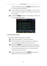
Page 13: ...ortcut interface will display 2 Turn the knob and a gray selection box appears Turn the knob to move the gray selection box 3 After selecting the certain parameter press the knob to confirm the input value Set values of voltage Set values of O V P Set values of O C P Set values of current 4 4 2 Edit To edit the channel parameters of M1 to M4 follow these steps 1 Press Memory key on front panel the...

Page 14: ...r the point is selected When the editing is completed the instrument can output the expected waveform according to the time sequence edited by the user 4 5 1 List waveform editing To edit the List output waveform the steps are as follows 1 Long press the Memory function key on the front panel for 3 seconds to enter the List waveform editing interface 2 In the non parameter setting state turn the k...

Page 15: ...perform List waveform output the steps are as follows 1 Follow the steps described in 1 1 to edit the List waveform 2 Enter List output mode at this time the first point of the List waveform pre output is displayed in the upper right corner such as List1 3 Short press the On Off function key on the front panel the instrument will output according to the List editing time sequence and the status ba...

Page 16: ...n turn on or turn off the automatic output at power on function by pressing and holding the On Off function key for 3 seconds The steps are as follows 2 When the automatic output at power on is turned off after power on the instrument is in the standby state The user needs to manually perform the On Off operation then the instrument will output 4 7 Display Press the Display function key to choose ...

Page 17: ...rve Curve Press the Display function key to set the display mode to Curve 5 Troubleshooting 1 The instrument is powered on but no Display Check if the power is connected properly Check if the fuse which is below the AC Power socket is used appropriately and in good condition the cover can be pried open with a straight screwdriver Restart the instrument after the steps above ...

Page 18: ...t it to other value If the problem still exists please contact us for our service 6 Appendix 6 1 Appendix A Accessories The accessories subject to final delivery standard Power Cord User Manual Fuse optional Banana plug to crocodile clip test leads 6 2 Appendix B General Care and Cleaning General Care Do not store or leave the instrument where the liquid crystal display could be exposed to direct ...

Page 19: ...tection screen when cleaning Disconnect power before cleaning your instrument Clean the instrument with a damp soft cloth not dripping with water It is recommended to clean with soft detergent or fresh water To avoid damage to the instrument do not use any corrosive chemical cleaning agents Warning Before re applying power ensure that the instrument is completely dry avoiding any electric shock or...

Reviews: