18
PVC Components
IMPORTANT NOTES:
• Before permanently installing these components, it is
recommended you dry-fit them first to ensure proper
fit and alignment with other vent pipes.
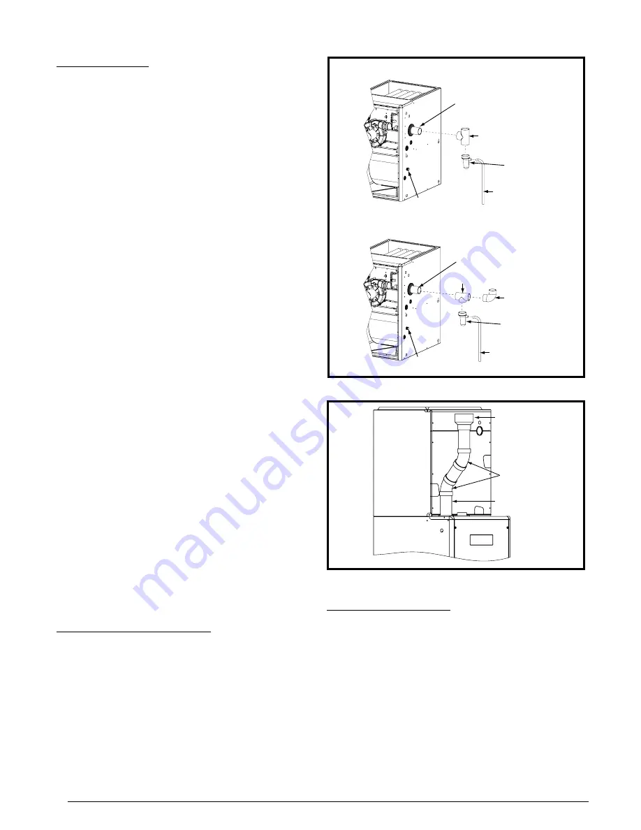
• The 2” PVC components shown in
provided in the extra parts bag for *SC & *SL models.
However the PVC Trap (P/N 664659) can be purchased
thru your local distributor.
The 2” PVC tee, reducer, PVC Trap and 1/2” X 1/2” hose
barb are used when the inducer is rotated to vent out thru
the left or right side of the furnace cabinet. See
.
The 1/2” X 3/4” hose barb can be used to route the condensate
drain to the outside of the cabinet. It must be installed from
inside the cabinet with the threaded end inserted thru the 1
1/16” hole. The condensate drain should be connected to
the barbed end. Attach 1” PVC drain line to the threaded
end. See
hole location.
Typical Orientation
1. Install the PVC Tee vertically on the 2” vent pipe that is
extending out the side of the cabinet. Permanently bond
them together using appropriate primer and cement. Refer
to the typical orientation shown in
.
2. Install the reducer or PVC trap (if supplied) on the bottom
end of the PVC Tee. Permanently bond them together
using appropriate primer and cement.
3. Install the 1/2” x 1/2” hose barb on the 2” PVC reducer.
NOTE
: Do not over tighten! Use an adequate amount of
Teflon tape on the threads. Do not use liquid sealants.
4. Verify all connections and joints for tight fit and proper
alignment with other vent pipes.
Alternate Orientation
1. Install the 2” PVC Tee horizontally on the 2” vent pipe that
is extending out the side of the cabinet. Permanently bond
them together using appropriate primer and cement. Refer
to the alternate orientation shown in
.
2. Install the 2” PVC Elbow on the end of the 2” PVC Tee.
Permanently bond them together using appropriate primer
and cement.
3. Install the reducer or PVC trap (if supplied) on the bottom
end of the PVC Tee. Permanenly bond them together using
appropriate primer and cement.
4. Install the 1/2” x 1/2” hose barb on the 2” PVC reducer.
NOTE
: Do not over tighten! Use an adequate amount of
Teflon tape on the threads. Do not use liquid sealants.
5. Verify all connections and joints for tight fit and proper
alignment with other vent pipes.
Optional PVC Pipe Installation
When running the 2” PVC pipe out through the top of the
J951X*U upflow furnace, there may be possible clearance
issues when transitioning the PVC pipe from 2” to 3”:
• If the size of the PVC flue needs to be increased from 2”
to 3”, two, 2” x 45° PVC elbows may be used to achieve
the clearances needed between the coil box and the 2” x
3” coupling. See
• Install the 2” x 3” coupling in the vertical run only. If the
coupling is installed horizontally, it will allow water to build
up inside the furnace and cause a lock out condition.
• To avoid the clearance issue, it is recommended that the
furnace be vented through the left side or the right side of
the cabinet.
1/2” x 3/4”
Hose Barb
2” PVC Elbow
(Field Supplied)
2” PVC Tee
1/2” x 3/4”
Hose Barb
2” PVC Pipe from Inline
Drain Assembly
(Not Included)
INSTALLATION OF PVC COMPONENTS
(TYPICAL ORIENTATION)
INSTALLATION OF PVC COMPONENTS
(ALTERNATE ORIENTATION)
2” PVC Tee
2” PVC Pipe from Inline
Drain Assembly
(Not Included)
1/2” Tubing (Field Supplied)
Drain Line Attached
to PVC Trap
(Do Not Trap)
1/2” Tubing (Field Supplied)
Drain Line Attached
to PVC Trap
(Do Not Trap)
PVC TRAP
Not Included in
*SC & *SL Models
PVC TRAP
Not Included in
*SC & *SL Models
Figure 19. PVC Components
Figure 20. Optional PVC Pipe Installation
2” x 45
0
PVC
Elbow
2” PVC Pipe
2” x 3” PVC
Coupling
Coil Box
Condensate Drain Lines
If the furnace is installed in an area where temperatures
fall below freezing, special precautions must be made
for insulating condensate drain lines that drain to the
outdoors. If condensate freezes in the lines, this will
cause improper operation or damage to the furnace. It
is recommended that all drain lines on the outside of
the residence be wrapped with an industry approved
insulation or material allowed by local code.
• The method for disposing condensate varies according to
local codes. Consult your local code or authority having
jurisdiction.
• The condensate drain line must be trapped using a kit
(P/N- 922485) or field supplied parts. After the drain trap,
condensate can continue to the drain by connecting to a
recommended 3/4” ID minimum drain line, but no smaller


