3
4
Meter Description
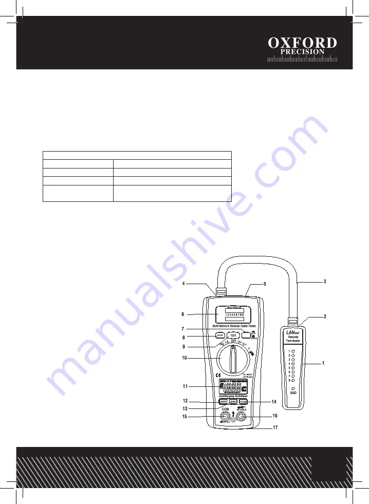
LANtester part Description (1~9) :
1. Remote terminator with LED display for receiving end
2. Jack RJ45
3. LAN-connector
4. Jack RJ45
5. Jack RJ45
6. Led display for sourcing end (Jack 1)
Safety information
1.
Improper use of this Multimeter can cause damage, shock, injury or death. Read and
understand this operator’s manual before operating the Multimeter.
2. Make sure any covers are properly closed and secured.
3. Always disconnect the test leads from any voltage source before replacing the batteries
or fuses.
4. Do not exceed the maximum rated input limits.
5. Use great care when making measurements if the voltages are greater than 25VAC rms or
35VDC. These voltages are considered a shock hazard.
6. Always discharge capacitors and remove power from the device under test before performing
Diode, Resistance or Continuity tests.
7.
Remove the batteries if the Multimeter is to be stored for long periods.
PRODUCT FEATURES
LAN tester part Description (1~9) :
1.
Remote terminator with LED display
for receiving end
2. Jack RJ45
3. LAN-connector
4. Jack RJ45
5. Jack RJ45
6. Led display for sourcing end (Jack 1)
& Led display for receiving end (Jack 2)
7.
Test switch for auto scan
8. LAN tester Power switch
9. Test switch for manual scan
Digital Multimeter part Description (10~17) :
10. Function switch
11. 3 1/2 Digit (2000 count) LCD display
for DMM functions
12. MODE button
13. MAX Hold button
14. Data Hold button
15. COM input jack
16. V,
Ω
,
µ
A, mA input jack
17. Battery Cover
3
manual for further information.
This symbol, adjacent to a terminal, indicates
that, under normal use, hazardous voltages
may be present.
Double insulation
Safety Precautions
1. Improper use of this meter can cause damage, shock,
injury or death. Read and understand this user’s manual
before operating the meter.
2. Make sure any covers or battery doors are properly
closed and secured.
3. Always disconnect the test leads from any voltage
source before replacing the battery or fuses.
4. Do not exceed the maximum rated input limits.
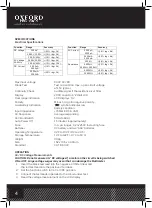
Input Limits
Function
Maximum Input
V DC or V AC
600V DC/AC
µA AC/DC
200mA/250V fast acting Fuse
Resistance,Diode
& Continuity Test
600V DC/AC
5.
Use great care when making measurements if the
voltages are greater than 25VAC rms or 35VDC. These
voltages are considered a shock hazard.
6.
Always discharge capacitors and remove power from
the device under test before performing Diode,
Resistance or Continuity tests.
7.
Remove the battery from the meter if the meter is to be
stored for long periods.


