4
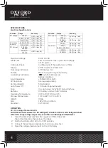
SPECIFICATIONS
Electrical Specifications
Max input voltage
600V AC/DC
Diode Test
Test current 1mA max., open circuit voltage
of 1.5V typical
Continuity Check
Audible signal if the resistance is <150
Ω
Display
2000 count 3 -1/2 digit LCD
Over range indication
LCD displays “OL”
Polarity
Minus (-) sign for negative polarity.
Low Battery Indication
“
” symbol indicates low
battery condition.
Input Impedance
>7.5M
Ω
(VDC & VAC)
AC Response
Average responding
ACV Bandwidth
50Hz to60Hz
Auto Power Off
15 minutes (approximately)
Fuse
mA, µA ranges; 0.2A/250V fast acting fuse
Batteries
9V battery and two “AAA” batteries
Operating Temperature
32°F to 104°F (0°C to 40°C)
Storage Temperature
14°F to 122°F (-10°C to 50°C)
Weight
308g
Size
162 x 74.5 x 44.0mm
Standard
CAT III 600V
OPERATION
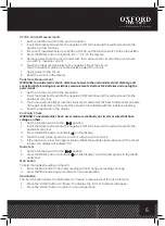
AC/DC Voltage Measurements
CAUTION: Do not measure AC/ DC voltages if a motor on the circuit is being switched
ON or OFF. Large voltage surges may occur that can damage the Multimeter.
1.
Insert the black test lead into the negative COM terminal and
the red test lead into the positive V terminal.
2. Set the function switch to VAC or VDC position.
3. Connect the test leads in parallel to the circuit under test.
4. Read the voltage measurement on the LCD display.
5
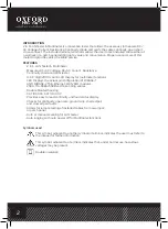
& Led display for receiving end (Jack 2)
7. Test switch for auto scan
8. LAN tester Power switch
9. Test switch for manual scan
Digital multimeter part Description (10~17) :
10. Function switch
11. 3 1/2 Digit (2000 count)LCD display for DMM functions
12. MODE button
13. MAX Hold button
14. Data Hold button
15. COM input jack
16. V,
Ω
,uA,mA input jack
17. Battery Cover
Specifications
Electrical Specifications
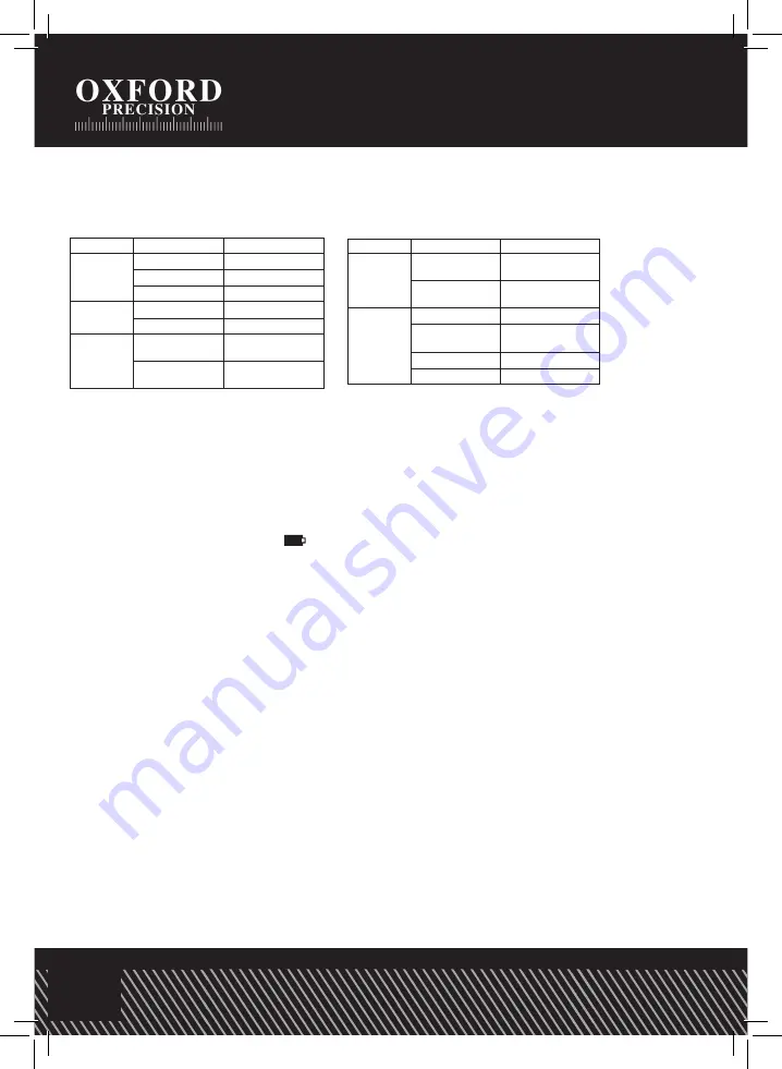
Function
Range
Accuracy
DC Voltage
200mV,
±
(0.5% rdg + 3d)
2.000V, 20.00V,
±
(1.0% rdg + 3d)
200.0V, 600V
±
(1.0% rdg + 3d)
AC Voltage
50-60Hz
2.000V, 20.00V
±
(1.0% rdg + 5d)
200.0V, 600V
±
(1.5% rdg + 10d)
DC Current
200.0µA,
2000µA
±
(1.5% rdg + 3d)
20.00mA,
200.0mA
±
(2.0% rdg + 3d)
6
AC Current
200.0µA,
2000µA
±
(1.8% rdg + 8d)
20.00mA,
200.0mA
±
(2.5% rdg + 8d)
Resistance
200.0
Ω
±
(0.8% rdg + 5d)
2.000k
Ω
,
20.00k
Ω
, 200.0k
Ω
±
(1.2% rdg + 3d)
2.000M
Ω
±
(2.0% rdg + 5d)
20.00M
Ω
±
(5.0% rdg + 8d)
Max input voltage
600V AC/DC
Diode Test
Test current 1mA max., open circuit
voltage of 1.5V typical
Continuity Check
Audible signal if the resistance is <150
Ω
Display
2000 count 3 -1/2 digit LCD
Over range indication
LCD displays “OL”
Polarity
Minus (-) sign for negative polarity.
Low Battery Indication
“BAT” symbol
indicates low battery condition.
Input Impedance
>7.5MΩ (VDC & VAC)
AC Response
Average responding
ACV Bandwidth
50Hz to60Hz
Auto Power Off
15 minutes (approximately)
Fuse
mA, µA ranges; 0.2A/250V fast acting
fuse
Batteries
9V battery and two “AAA” batteries
Operating Temperature
32
o
F to 104
o
F (0
o
C to 40
o
C)
Storage Temperature
14
o
F to 122
o
F (-10
o
C to 50
o
C)
Function
Range
Accuracy


