background image

3

3

6

9

10

8

4

10A

A

mA

V

Ω

¡ ã

¡ ã

μ

11

12

7

REL

1

2

AC

Hz%

DC

AUTO

Hz%

kM

5

hazardous voltages. For maximum safety, the meter 
and its test leads should not be handled when these 
terminals are energized.

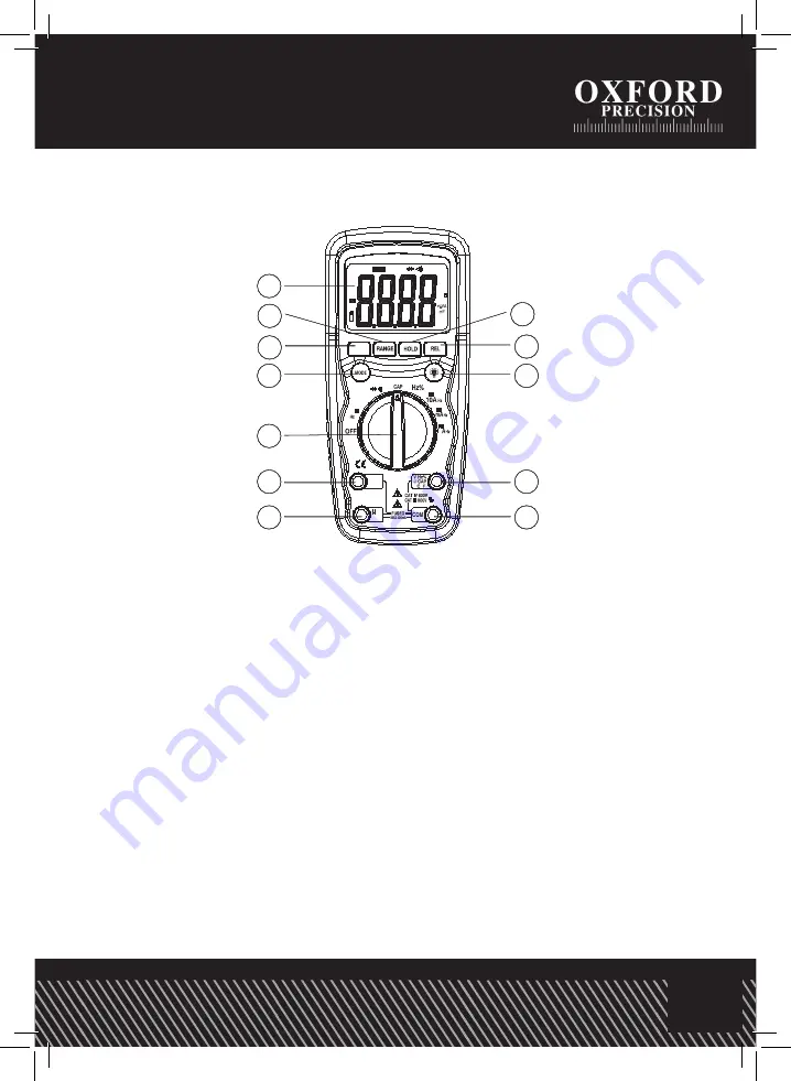
CONTROLS AND JACKS

1.

Large 4000 count Liquid Crystal Display 

with symbolic signs.

2.

Range pushbutton.

PRODUCT FEATURES

1.  Large 4000 count Liquid Crystal Display with symbolic signs
2. Range push button
3. Frequency/ % Duty button
4. Mode push button
5. Data Hold push button
6. Relative push button
7. Backlight push button
8. Function switch
9. 10A (positive) input jack 
10. µA/mA input jack
11.  Positive input jack for DC/AC Voltage, Hz/%duty cycle, Ohms, Diode, Continuity, 

Capacitance measurements

12. COM (negative) input jack

Summary of Contents for OXD-516-6487F

Page 1: ...RATOR S MANUAL ORDER CODE OXD 516 6487F CZ HU PL SK TH cromwell co uk Auto Ranging Data hold function Relative zero mode Auto power off and low battery indication Backlight Tilt Stand CAT III 1000V CA...

Page 2: ...rdous situation which if not avoided could result in death or serious injury This CAUTION symbol indicates a potentially hazardous situation which if not avoided may result damage to the product This...

Page 3: ...ay with symbolic signs 2 Range pushbutton PRODUCT FEATURES 1 Large 4000 count Liquid Crystal Display with symbolic signs 2 Range push button 3 Frequency Duty button 4 Mode push button 5 Data Hold push...

Page 4: ...tage category CAT III 1000V CAT IV 600V Display 4000 counts LCD display with function indication Polarity Automatic negative polarity indication Over range OL mark indication Low battery indication Th...

Page 5: ...0 0uA 0 1 A 1 0 of rdg 3 dgts 4000uA 1 A 1 5 of rdg 3 dgts 40 00mA 10 A 400 0mA 100 A 10A 10mA 2 5 of rdg 5 dgts Overload Protection 0 5A 1000V and 10A 1000V Fuse Maximum Input 400mA dc or 400mA ac rm...

Page 6: ...acitance Auto ranging Range Resolution Accuracy 4 000nF 1pF 5 0 of rdg 20 dgts 40 00nF 10pF 5 0 of rdg 7 dgts 400 0nF 0 1nF 3 0 of rdg 5 dgts 4 000uF 1nF 40 00uF 10nF 100 0uF 0 1 F 5 0 of rdg 5 dgts I...

Page 7: ...automatically selects the best range for the measurements being made and is generally the best mode for most measurements For measurement situations requiring that a range be manually selected perfor...

Page 8: ...tips to the circuit under test Be sure to observe the correct polarity red lead to positive black lead to negative 4 Read the voltage in the display The display will indicate the proper decimal point...

Page 9: ...e side of the circuit Touch the red test probe tip to the positive side of the circuit 8 Apply power to the circuit 9 Read the current in the display The display will indicate the proper decimal point...

Page 10: ...lead banana plug into the positive jack 3 Touch the test probe tips across the circuit or part under test It is best to disconnect one side of the part under test so the rest of the circuit will not i...

Page 11: ...G To avoid electric shock disconnect the test leads from any source of voltage before removing the battery cover 1 Disconnect the test leads from the Multimeter 2 Open the battery cover by loosening t...

Page 12: ...ctrical goods that have reached the end of their life must be collected separately and returned to an environmentally compatible recycling facility Do not dispose of electrical goods with domestic was...

Reviews: