Cube С-02 turnstile
12
4.2
Installation of turnstile
Diagram of the turnstile and its connection is shown in the Appendix 3
4.2.1
Prepare surface at the installation site of the turnstile.
4.2.2
Open and unpack the box:
•
Blocking arms unit
•
Wall mount bracket
•
PS with a cable
4.2.3
Prepare cable conduit coming from the site to the installation
area of PS, remote control panel, and as well, if it is required, to
the connection point of ACS and SFAS
.
4.2.4
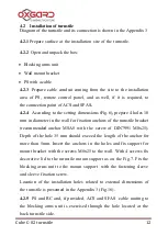
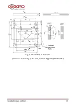
According to the setting dimensions (Fig.6), prepare 4 holes 10
mm in diameter in the wall for fixation anchors of the turnstile bracket
(recommended anchor MSA8 with the screw of DIN7991 M8x25).
Depth of the hole 35 mm should exceed the length of the anchor for
more than 5mm. Insert the anchors in the holes and fix support for
mount bracket with the screws
М8х25 to the wall. With 4 screws fix
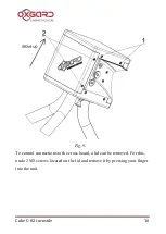
decorative lid to the turnstile mount support as on the Fig.7. Fix the
blocking arms unit to the mount support with the fastening sleeve
and sleeve fixation screw.
Location of the installation holes related to external dimensions of
the turnstile is presented in the Appendix 3 (Fig.16).
4.2.5
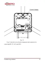
PS and RC and, if provided, ACS and SFAS cable routing to
the blocking arms unit is exercised through the hole located at the
back turnstile side.
Summary of Contents for Cube C-02
Page 1: ...Installation guidelines www oxgard com info oxgard com Tel 7 812 366 15 94 Cube 02 turnstile...
Page 2: ......
Page 26: ...Cube 02 turnstile 26 Fig 15 Connecting diagram of control panel to ACS controller...
Page 29: ...Installation guidelines 29 Appendix 3 Diagram of the turnstile and its connection...
Page 30: ...Cube 02 turnstile 30...
Page 31: ...Installation guidelines 31...


