Installation guidelines
23
through 60 grades and turns back to the initial position after complete
passage fulfillment.
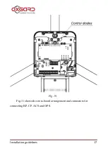
To check the operation of the motherboard, there are mounted Light
Emitting Diodes (LED). To check their operation, it’s necessary to
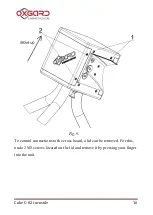
remove the cover (Fig.10). Fig. 12 shows the arrangement of the LED
D5 that indicates a signal to the input “LEFT”.
D6 that indicates a signal to the input “RIGHT”.
D7 indicates a signal to the input “STOP”.
D10 indicates a passage fulfillment to the right and relay activation
(Ok-1 to the right).
D16 indicates a passage fulfillment to the left and relay activation
(Ok-2 to the left).
D15 indicates powering 12V of the motherboard.
D12 EnDec and D13 EncInc indicate the right arrangement of the magnet
relative to the barrier arms position magnetic sensor. Located right D12
and D13 are not lightened.
5.4. Connecting control panel to ACS controller
In some cases remote control panel must be connected directly to ACS
controller, as the passages, permitted by control panel (without controller),
are regarded by the system as “forced entry”.
To use this turnstile connection scheme it is required to install a jumper
X3 (Remote Control) to the motherboard in position «On» (Fig.12). With
X3 jumper installed the turnstile does not react to the signals coming from
the control panel but transmits their state to the contacts of the terminals
Summary of Contents for Cube C-02
Page 1: ...Installation guidelines www oxgard com info oxgard com Tel 7 812 366 15 94 Cube 02 turnstile...
Page 2: ......
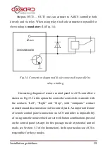
Page 26: ...Cube 02 turnstile 26 Fig 15 Connecting diagram of control panel to ACS controller...
Page 29: ...Installation guidelines 29 Appendix 3 Diagram of the turnstile and its connection...
Page 30: ...Cube 02 turnstile 30...
Page 31: ...Installation guidelines 31...


