background image


Cube С-02 turnstile 

 24 

OUT1… OUT3 of the crossboard (Fig.11), which are the outputs with bare 

collector. Contact assignment is represented in Table 6, numbering of the 

control panel buttons is shown on Fig.13.  For this group of contacts 

maximum output current does not exceed 150 m

А, permissible voltage is no 

more than 24 V. 


Fig. 13. Numbering of control panel buttons 


Table 6. Assignment of  OUT contact group


Contact 

marking 

Assignment of contacts 

OUT1 

Status of “Left” button (1,Fig 13) 

OUT2 

Status of “Right” button (3,Fig.13) 

OUT3 

Status of “Stop” button (2, Fig.13) 

 
Outputs OUT1… OUT3 display current status of remote control panel 

buttons, i.e. the transistor opens when the appropriate button is pressed.  

Summary of Contents for Cube C-02

Page 1: ...Installation guidelines www oxgard com info oxgard com Tel 7 812 366 15 94 Cube 02 turnstile...

Page 2: ......

Page 3: ...1 Required equipment 11 4 2 Installation of turnstile 12 5 Connecting turnstile 15 5 1 Power connection 19 5 2 Connecting Control Panel 20 5 3 Connecting ACS optionally 20 Appendix 1 Summary of data...

Page 4: ...4 List of abbreviations used PS Power Supply SFAS Security and Fire Alarm RC Remote Control Panel System ACS Access Control System NC normally connected NO normally opened Firmware version of turnsti...

Page 5: ...Relative humidity no more 80 80 Passage width mm 500 Throughput person min 30 Lifetime years 8 8 Table 2 Electrical characteristics Specification Turnstile Panel Power supply voltage V rated working 1...

Page 6: ...arms Housing and blocking arms are made of brushed stainless steel Wall mount bracket Wall mount bracket designated to secure arms block fixation to the turnstile installation sight Arms block and br...

Page 7: ...ges it is required to arrange passage zones as per Fig 2 Recommended installation diagram Not recommended installation diagram Fig 2 Arrangement of turnstile passage zone When installing the turnstile...

Page 8: ...ation panel Indication panel of the turnstile is located at the upper part of the turnstile behind the insert made of acryl glass Operation modes of the turnstile are displayed on the panel in form of...

Page 9: ...cation panel Control panel Housing of remote control panel is made of brushed stainless steel In the front there are control buttons and LEDs indicating operation modes of the panel Fig 5 Standard cab...

Page 10: ...cated in this Section may cause damage to life and health of people complete or partial loss of operating capability of the product and or auxiliary equipment ATTENTION The manufacturer shall disclaim...

Page 11: ...the screw of DIN7991 M8x25 S5 internal hex wrench for screws slotted screwdriver plummet or leveling gauge steel liners for turnstile aligning side cutters ATTENTION The turnstile should be installed...

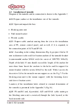
Page 12: ...for fixation anchors of the turnstile bracket recommended anchor MSA8 with the screw of DIN7991 M8x25 Depth of the hole 35 mm should exceed the length of the anchor for more than 5mm Insert the ancho...

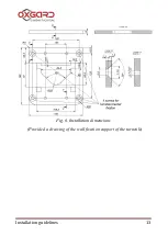
Page 13: ...Installation guidelines 13 Fig 6 Installation dimensions Provided a drawing of the wall fixation support of the turnstile...

Page 14: ...Cube 02 turnstile 14 Fig 7 Installation diagram of the turnstile bracket support 4 2 6 Remove protective film from the turnstile housing...

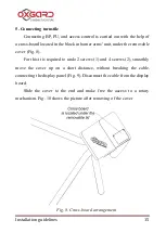
Page 15: ...ovable cover Fig 8 For this it is required to undo 2 screws 1 and 4 screws 2 smoothly move the cover up on a short distance without breaking the cable connecting the display panel Fig 9 Disconnect the...

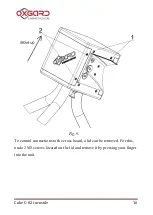
Page 16: ...Cube 02 turnstile 16 Fig 9 To control connections to the cross board a lid can be removed For this undo 2 M3 screws located on the lid and remove it by pressing your finger into the unit...

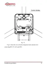
Page 17: ...Installation guidelines 17 Fig 10 Fig 11 shows the cross board arrangement and connectors for connecting BP CP ACS and OPS...

Page 18: ...ode X1 Position On Potential mode see i 5 3 X1 Position OFF Pulse mode see i 5 3 Remote Control X3 Position On Turnstile does not react to the control panel instructions button status translated to th...

Page 19: ...or an access of the operator Connect PS cable to POWER group of the contacts 12U_IN and GND_IN located on the cross board The contacts and of PS to be connected to the contacts 12V_IN and GND_IN corre...

Page 20: ...TE CONTROL PANEL connection Contact marking Colour of wire 12V Red CL Yellow CH Green GND Blue 5 3 Connecting ACS optionally ACS Controller will have to be connected to the group of contacts Control l...

Page 21: ...one or another side If both inputs are closed the pass will be allowed to the side which input closed first In case the pass fails to be done the turnstile will automatically change over to Stop mode...

Page 22: ...RIGHT Free passage mode one can set by control signal supply to both of the inputs simultaneously The priority of the inputs LEFT and RIGHT while changing over to a pulse mode will remain unchanged On...

Page 23: ...t and relay activation Ok 2 to the left D15 indicates powering 12V of the motherboard D12 EnDec and D13 EncInc indicate the right arrangement of the magnet relative to the barrier arms position magnet...

Page 24: ...ut current does not exceed 150 m permissible voltage is no more than 24 V Fig 13 Numbering of control panel buttons Table 6 Assignment of OUT contact group Contact marking Assignment of contacts OUT1...

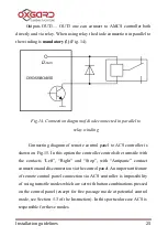
Page 25: ...ller is shown on Fig 15 In this option the controller controls the turnstile with the contacts Left Right and Stop with Antipanic contact connection and disconnection via the control panel An importan...

Page 26: ...Cube 02 turnstile 26 Fig 15 Connecting diagram of control panel to ACS controller...

Page 27: ...or Cat6 Total electrical resistance for power wire of the remote control panel for direct current shall not exceed 50 Ohm If this requirement is unable to comply with one can install additional PS for...

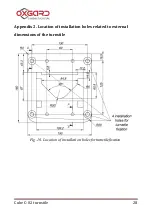
Page 28: ...Cube 02 turnstile 28 Appendix 2 Location of installation holes related to external dimensions of the turnstile Fig 16 Location of installation holes for turnstile fixation...

Page 29: ...Installation guidelines 29 Appendix 3 Diagram of the turnstile and its connection...

Page 30: ...Cube 02 turnstile 30...

Page 31: ...Installation guidelines 31...

Page 32: ...OOO Vozrozhdenie 66 Sofiyskaya str 192289 Saint Petersburg tel fax 7 812 336 15 94 www oxgard com info oxgard com...

Reviews: