Installation guidelines
13
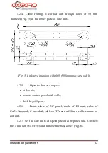
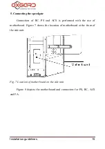
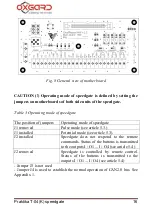
4.2.4. Cable routing is carried out through holes of 50 mm
diameter (Fig. 5) in the lower plate of side units.
Fig. 5. Linkage dimension with 660 (900) mm passage width
4.2.5.
Open the box and unpack:
•
side units;
•
remote control panel with cable;
•
lock keys (8 pcs.).
4.2.6.
Route cable of RC panel, cable of PS unit, cable of
CAN-Bus, and, if provided, cables of FA and ACS into cable channel or
conduit.
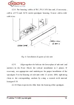
4.2.7. Set the side units of speedgate on a prepared site. Unscrew
the 4 units of M4 screws and remove the base cover (Fig. 6).


