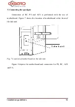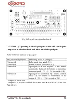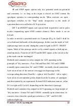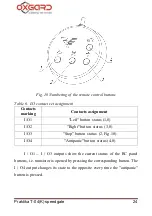
Praktika T-04(K) speedgate
14
4.2.8. Put housing cables of RC, PS, CAN-bus and, if necessary,
cables of FA and ACS inside speedgate housing. Secure cables with
cable ties.
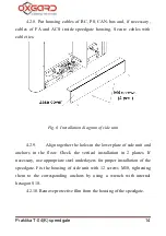
Fig. 6
Installation diagram of side unit
4.2.9.
Align together the holes in the lower plate of side unit and
anchors in the floor. Check the vertical installation in 2 planes. If
necessary, use appropriate steel underlayers for proper installation of the
speedgate. Fix the housing of side unit with 12 screws M10, tightening
them to the corresponding anchors by using a wrench with internal
hexagon S10.
4.2.10. Remove protective film from the housing of the speedgate.


