Praktika T-04(K) speedgate
20
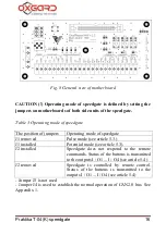
Connect «CL» «CH» «GND» contacts of motherboard located in unit
"A" housing (marked No. 1) with the same contacts of motherboard
located in unit B housing (marked No. 4). See Fig. 9.
«CL» «CH» «GND» contacts of motherboard located in unit “B”
(marked No. 3) shall be connected to the same contacts of motherboard
located in unit “C” (marked No. 6). See fig. 9.
Control panels RC1 and RC2 are connected to pins «+ U» «CL»
«CH» «GND» of corresponded unit.
If RC panels are connected as shown in Fig. 9 jumpers shall be set as
follows for the proper operation of the bus CAN2.0 J4:
-J4 on the motherboard 1 is open, J4 on the motherboard 4 is closed
-J4 on the motherboard 3 is open, J4 on the motherboard 6 is closed
Detailed connection pattern of two units of speedgate is shown in
Appendix 6.
In order to provide the entrance with two passages you need four
power supply units 12V 5 A.
The middle unit is powered either by two power supply units 12V 5A
or by single power supply 12V 10A.
A card collector can be integrated in any side or middle units. It is
supposed to be installed "the right hand" from the output side.
Card collector can be installed only at the factory!
5.4. Connecting access control system (optional)
ACS controller is connected to AccessControlSystem contact set on
motherboard. Marking of contacts: LEFT, RIGHT, STOP, AP, GND.
Contact assignment shown in table 5.


