Installation guidelines
23
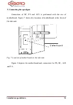
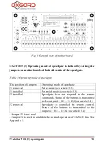
Also the motherboard contains following LED indicators:
D4 indicates a signal to the «LEFT» input.
D5 indicates a signal to the «RIGHT» input.
D6 indicates signal to the «STOP» input.
D7 indicates a signal to the «AP» input.
5.5. Connecting RC panel to ACS controller
In some cases RC shall be connected directly to the ACS controller
as the passages allowed from the remote (without controller) are regarded
by the system as a "forced entry".
To use this connection pattern of speedgate J2 jumpers shall be set on
both motherboards of chosen passage (Fig. 8). When J2 jumpers are set the
speedgate does not respond to remote control commands but only
transmits their status to contacts of I / O1 ... I / O4 terminal boards (Fig. 8)
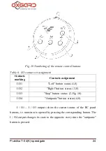
which are open collector outputs. Contacts assignment is shown in Table
5. The numbering of the remote control buttons is shown in Fig. 10. The
maximum output current for this set of contacts is 150 mA, maximum
voltage rating is 24 W.


