Praktika T-04(K) speedgate
40
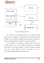
Fig. 21. Block diagram
№
3
The block diagram #3 (Fig. 21) can be considered to be a logical
development of the block diagram #2. It reduces the cost of installed
system. For this purpose the controller with two output signals to one input
of a reader (i.e., the controller can distinguish the guest cards and
permanent cards transmitting a signal to the corresponding output) is used.


