Installation instructions
15
PROTECTING THE FUTURE
necessary information.
The equipment shall be attached to the foundation before the
operation starts!
The original manufacturer shall not take responsibility for emergencies or
failures resulted from improper fixture of the equipment.
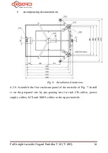
4.2.5. Install the C clamps of Fig. 20 by means of the bolts with anchors
(not included in the scope of supply) in the locations for fixturing of the
turnstile. Tighten the bolts to fix the expanding anchors in the soil.
4.2.6. Select a rack of the fixed enclosure panel, along which cables for
control and power supply of the turnstile will be laid to the upper module.
Prepare the cable channel from the site to the installation location of the
CB and, if required, to the place of connection of ACS and S&FA.
The cables shall be led to the upper module through the openings made
in the racks of the fixed enclosure panel (Fig. 2). It is necessary to
prepare a trench for that rack of the fixed module which will be used by
you to lay cables to the upper module.
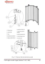
4.2.7. Open the box and unpack the turnstile, check the scope of supply for
the following:
part of the fixed enclosure panel (1);
parts of the mobile enclosure elements (rotatory wicket door)
(2);
parts of the fixed enclosure elements (3);
parts of the upper module (4);
actuator(5);
CB with a cable;
keys for the door lock (4 pieces);
Summary of Contents for Praktika T-10
Page 2: ...PROTECTING THE FUTURE...
Page 7: ...Installation instructions 7 PROTECTING THE FUTURE Fig 1 Initial position of the leaves...
Page 21: ...Installation instructions 21 PROTECTING THE FUTURE...
Page 26: ...Full height turnstile Oxgard Praktika 10 T 10H 26 PROTECTING THE FUTURE Fig 14 220 V 12 V...
Page 37: ...Installation instructions 37 PROTECTING THE FUTURE Fig 21 Sample for turnstile installation...
Page 39: ...Installation instructions 39 PROTECTING THE FUTURE...


