Installation instructions
35
PROTECTING THE FUTURE
Appendix 1. Short summary of the data transmission bus CAN2.0
The CB is operated by the up-to-date noise-resistant bus under the
standard CAN2.0. According to the standard CAN2.0 the length of the
cable for transmitting signals can reach more than one kilometer, but
correct operation at such distances depends on many factors. At distances
more than 25 meters the twisted pair Cat5e or Cat6 must be used. Total
electrical resistance in the wire for DC power supply to CB shall not
exceed 50 Ohm. If this requirement cannot be met, an additional
12 V/100 mA power supply unit can be installed at the place where the
control board is installed (with minimum operating power supply voltage
to CB equal to 7.5 V). In this situation 3 wires from the turnstile, i.e. CL,
CH, GND, are sufficient for correct operation. Two control boards can be
connected to one turnstile.
The CAN2.0 bus has an important feature by available 120 Ohm
resistors at the bus ends. The standard CB is already fitted with such a
resistor. When using one control board it is recommended to connect an
additional (second) 120 Ohm resistor, located at the cross-board to the
terminals CL and CH, by setting jumper J4.
It is not required to do so, if two control boards are to be connected, as the
bus ends are already fitted with the required resistors. And jumper J4 shall
be removed.
Summary of Contents for Praktika T-10
Page 2: ...PROTECTING THE FUTURE...
Page 7: ...Installation instructions 7 PROTECTING THE FUTURE Fig 1 Initial position of the leaves...
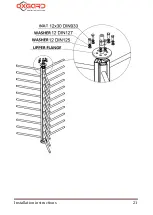
Page 21: ...Installation instructions 21 PROTECTING THE FUTURE...
Page 26: ...Full height turnstile Oxgard Praktika 10 T 10H 26 PROTECTING THE FUTURE Fig 14 220 V 12 V...
Page 37: ...Installation instructions 37 PROTECTING THE FUTURE Fig 21 Sample for turnstile installation...
Page 39: ...Installation instructions 39 PROTECTING THE FUTURE...


