Installation instructions
25
PROTECTING THE FUTURE
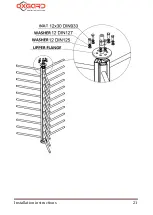
The upper cover shall be attached to the upper module by means of four
nuts (4) and four washers (Fig. 13). Four pins for fixing the upper cover
are located internally of the cover.
Fig. 13.
Fixture of the upper cover
5. Connection of the turnstile:
The cables shall be led through a hole made in the rack of the fixed
enclosure panel of the turnstile (Fig. 2). Fix the cable with cable ties.
220 V power supply shall be connected to the terminals located on
the DIN rack. The connection diagram is shown on Fig. 14.
Summary of Contents for Praktika T-10
Page 2: ...PROTECTING THE FUTURE...
Page 7: ...Installation instructions 7 PROTECTING THE FUTURE Fig 1 Initial position of the leaves...
Page 21: ...Installation instructions 21 PROTECTING THE FUTURE...
Page 26: ...Full height turnstile Oxgard Praktika 10 T 10H 26 PROTECTING THE FUTURE Fig 14 220 V 12 V...
Page 37: ...Installation instructions 37 PROTECTING THE FUTURE Fig 21 Sample for turnstile installation...
Page 39: ...Installation instructions 39 PROTECTING THE FUTURE...


