Oxford Technical Solutions
14
Inputs and outputs
The RT1003 is capable of transmitting and monitoring a number of digital signals for the
purpose of synchronisation and event marking. The following section describes the inputs
and outputs available on the RT1003.
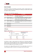
1PPS output
Figure 2.
1PPS waveform
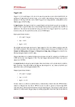
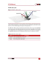
The 1PPS (J5-1) output is a pulse generated by the GNSS receiver. On RT1003 products, the
output is active even when the GNSS receiver has no valid position measurement. The falling
edge of the pulse is the exact transition from one second to the next in GPS time. The pulse is
low for 1 ms, then high for 999 ms and repeats every second.
The output is a low-voltage CMOS output, with 0.8 V or less representing a low and 2.4 V or
more representing a high. No more than 10 mA should be drawn from this output.
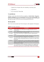
Table 7.
User cable digital I/O connector J5
Pin#
Name (function)
Description
J5-1
Digital 1 (1PPS output)
Pulsed output from primary GNSS receiver, synchronised with
the transition of GPS seconds
J5-2
Digital 2 (Trigger 1)
User-selectable I/O (input/distance output/IMU sync output)
J5-3
Digital 3 (Wheel speed 1A) Input for Hall-effect wheel speed sensor. When connecting a
quadrature sensor, this input is the A-channel
J5-4
Digital 4 (Trigger 2)
User-selectable I/O (input/distance output/IMU sync output)
J5-5
Digital 5 (Wheel speed 1B)
When connecting a quadrature wheel speed sensor, this input is
for the B-channel
J5-6
Digital ground
J5-7
Digital ground
J5-8
Digital ground
J5-9
Digital ground


